Water cooling system for cable protection pipe production

A cable protection tube and water-cooling system technology, which is applied in the direction of coating, etc., can solve the problems of low work efficiency, low water-cooling quality, and high labor intensity of operators, and achieve the effect of improving water-cooling efficiency and avoiding scatter

Pending Publication Date: 2022-03-18
江苏天菱电力设备有限公司
View PDF0 Cites 0 Cited by
  • Summary
  • Abstract
  • Description
  • Claims
  • Application Information

AI Technical Summary

Problems solved by technology

[0003] The purpose of the present invention is to overcome the problems of low work efficiency, high labor intensity of operators, low water cooling quality and low stability of cable protection tube in the water conservancy process in the existing water cooling device for cable protection tubes, and provide a reasonable structural design , high work efficiency, low labor intensity of operators, high water cooling quality, good stability of cable protection tube in water cooling process, cable protection tube production water cooling system

Method used


Image

  • Water cooling system for cable protection pipe production
  • Water cooling system for cable protection pipe production
  • Water cooling system for cable protection pipe production

Examples


Embodiment 1

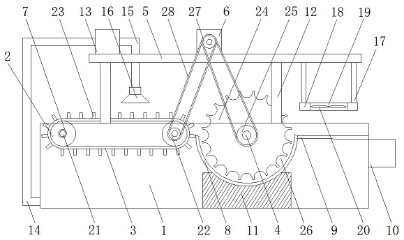
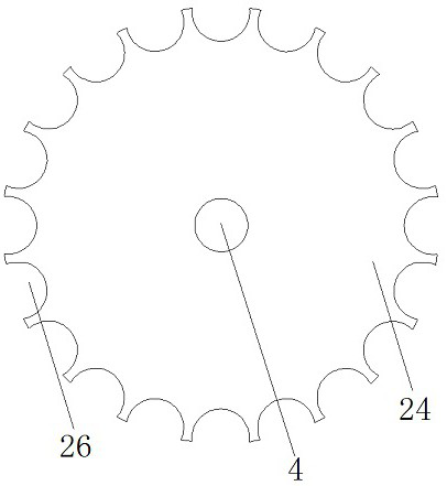
[0022] Append Figure 1-4 As shown, a cable protective tube is produced by water cooling system, including water tank 1, rotating roller 2, a transmission belt 3, a rotating shaft 4, a top plate 5, and a motor 6, characterized in that the water tank 1 is provided with bearing 7 The positioning groove 8 is provided on the inner wall of the water tank 1, and a fixing plate 9 is provided on the outer wall of the water tank 1, and a column 12 is provided at the top of the water tank 1, and the rotary roller 2 is provided with a connection. The shaft 21 is applied from the bearing 7 from the bearing 7, and is provided with a driven wheel one 22, and the transmission belt 3 is disposed between the rotating roller 2 and the rotating roller 2, the rotating shaft. 4 The two ends pass through the bearing 7, and the driven wheel 2 25 is provided at one end of the rotating shaft 4, and the dial 24 is provided on the rotating shaft 4, and the bottom end of the dial 24 is placed in the positioni...

Embodiment 2

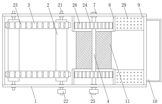
[0031] Append Figure 5 As shown: A cable protection tube production water-cooled system, including water tank 1, rotary roller 2, transmission belt 3, rotary shaft 4, top plate 5, and motor 6, characterized in that the water tank 1 is provided with bearing 7 The positioning groove 8 is provided on the inner wall of the water tank 1, and a fixing plate 9 is provided on the outer wall of the water tank 1, and a column 12 is provided at the top of the water tank 1, and the rotary roller 2 is provided with a connection. The shaft 21 is applied from the bearing 7 from the bearing 7, and is provided with a driven wheel one 22, and the transmission belt 3 is disposed between the rotating roller 2 and the rotating roller 2, the rotating shaft. 4 The two ends pass through the bearing 7, and the driven wheel 2 25 is provided at one end of the rotating shaft 4, and the dial 24 is provided on the rotating shaft 4, and the bottom end of the dial 24 is placed in the positioning groove 8, the Th...


PUM


Abstract

The invention discloses a water cooling system for cable protection pipe production, which comprises a water tank, rotating rollers, a transmission belt, a rotating shaft, a top plate and a motor, and is characterized in that a bearing is arranged on the side wall of the water tank, connecting shafts are arranged at the two ends of each rotating roller, the transmission belt is arranged between the rotating rollers, the two ends of each rotating shaft penetrate through the bearing, and the top plate is arranged on the top plate. The top plate is arranged on the stand columns, the motor is arranged on the top plate, and a driving wheel is arranged on the motor. According to the cable protection pipe water cooling device, cable protection pipes needing water cooling are placed on the conveying belt, the baffles on the conveying belt play a role in limiting the cable protection pipes, the cable protection pipes on the conveying belt move into the positioning grooves, the distribution grooves in the distribution disc enable the cable protection pipes to move in the positioning grooves in sequence, and the distribution grooves clamp the cable protection pipes to move in the positioning grooves; the cable protection pipes are prevented from being scattered in the positioning grooves, and the water cooling efficiency of the cable protection pipes and the stability in the water cooling process are improved.

Description

Technical field [0001] The present invention relates to the technical field of cable protection tube production, and is specifically a water-cooled system for production of cable protection tubes. Background technique [0002] In the prior art, during the processing of cable protection tubes, the production of cable protection tubes requires water-cooled treatment. The existing cable protection tube water-cooled process has low work efficiency. The operator's labor intensity is high, and the water is not high. Problems with high stability in the water cold process. Inventive content [0003] It is an object of the present invention to overcome the low work efficiency of the existing cable protection tube water-cooled device, the operational labor intensity, low water cooling quality, and the cable protection tube is not high in the water conservancy process, providing a structural design reasonable High work efficiency, operator's labor intensity, high water-cooled quality, cabl...

Claims


Application Information

Patent Timeline
Patent Type & Authority Applications(China)
IPC IPC(8): B29C48/355B29C48/88B29C48/09B29C37/00
CPCB29C48/355B29C48/9115B29C48/919B29C48/09B29C37/0092
Inventor 王笑笑
Owner 江苏天菱电力设备有限公司
Why Eureka
Try Eureka