Clothes processing equipment

A technology of clothing processing equipment and valve core, which is applied to other washing machines, washing machines with containers, washing devices, etc., can solve the problems of inability to achieve drainage, overloaded operation of motors, etc., and achieves simple structure, improved service life, and high reliability. Effect

Active Publication Date: 2022-03-18
WUXI LITTLE SWAN ELECTRIC CO LTD
View PDF19 Cites 2 Cited by
  • Summary
  • Abstract
  • Description
  • Claims
  • Application Information

AI Technical Summary

Problems solved by technology

[0004] In the above solution, the dehydration valve can only be opened when the inner cylinder rotates at a high speed. When the washing process in the inner cylinder is over, the inner cylinder contains a large amount of water, and the motor needs to drive the inner cylinder and the water in the inner cylinder to rotate at a high speed. Realize drainage; on the one hand, the inner cylinder cannot achieve drainage under low-speed rotation; on the other hand, it will overload the motor

Method used


Image

  • Clothes processing equipment
  • Clothes processing equipment
  • Clothes processing equipment

Examples


no. 1 example

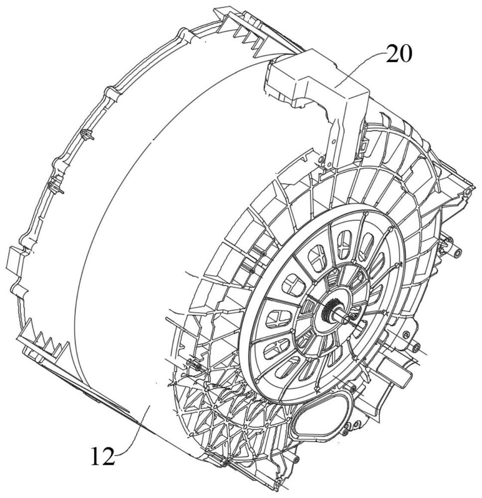
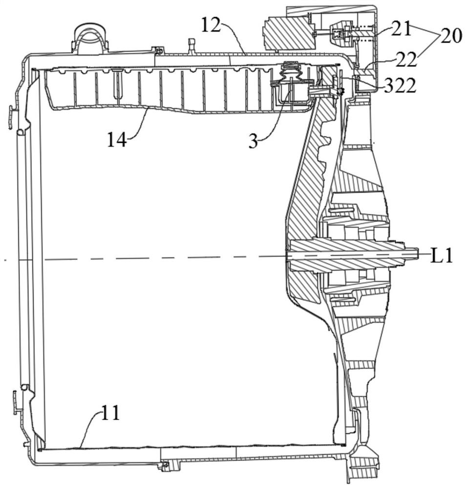
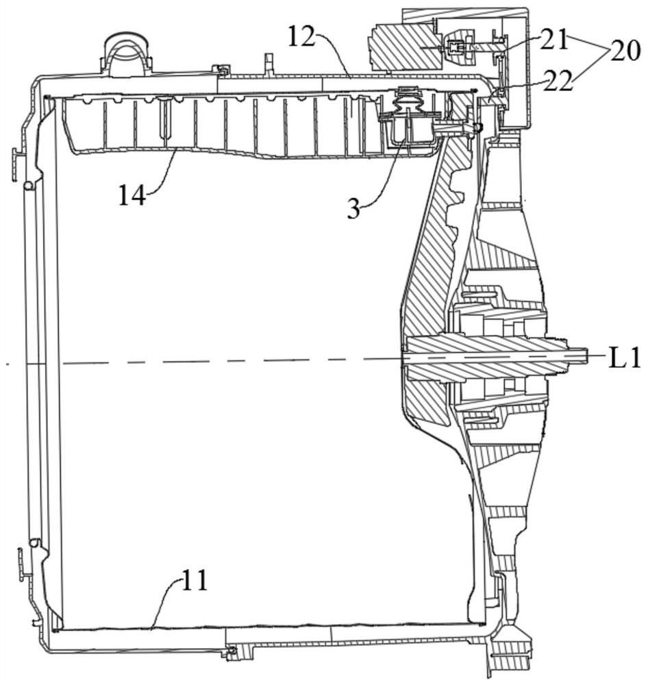
[0112] see Figure 8 to Figure 16 ,, In this embodiment, the transmission rod mechanism 32 drives the spool 31 assembly to move in translation.

[0113] The drain valve assembly 3 includes the above-mentioned transmission rod mechanism 32 , valve seat 35 , valve core 31 , flexible seal 36 , reversing mechanism 323 , first torsion spring 33 and second torsion spring 34 .

[0114] The first torsion spring 33 is sleeved on the transmission rod 321 . The first end of the transmission rod 321 has a flat shaft portion 3211 . The second end of the transmission rod 321 is socketed with the first driving rod 322 and can realize synchronous rotation.

[0115] The turntable 3231 is formed with a through hole 3231c, and the inner wall of the through hole 3231c is provided with two rotationally symmetrical protrusions 32311, and the two protrusions 32311 separate part of the space of the through hole 3231c into two first driving grooves 3231a distributed along the circumferential directi...

no. 2 example

[0121] see Figure 17 to Figure 21 Most of the structures of the embodiment of the present application are substantially the same as those of the first embodiment, the differences include: the structure of the second end of the transmission rod 321 , the structure of the reversing mechanism 323 , and the connection position of the second torsion spring 34 .

[0122] Specifically, the turntable 3231 is formed with a through hole 3231c, and the first driving groove 3231a passes through a part of the side wall of the through hole 3231c along the radial direction of the through hole 3231c, that is to say, the first driving groove 3231a is roughly in the shape of a gap, and the transmission rod 321 A protruding block 3212 is provided on the surface of the body, the transmission rod 321 is passed through the through hole 3231c, and the protruding block 3212 is located in the first driving groove 3231a.

[0123] The second torsion spring 34 and the reversing mechanism 323 are dispose...


PUM


Abstract

The embodiment of the invention provides clothes treatment equipment which comprises an inner barrel, a driving device and a drainage valve assembly, and the inner barrel can contain water and is provided with a drainage hole; the drainage valve assembly comprises a valve element, a transmission rod mechanism, an elastic positioning piece and an elastic reset piece. The valve element is provided with a sealing position and a drainage position. The first end of the transmission rod mechanism drives the valve element to move, and in the rotating process of the inner barrel, the driving device can selectively stir the second end of the transmission rod mechanism so as to drive the transmission rod mechanism to rotate around the rotating center line; the elastic positioning piece can maintain the valve element at the sealing position or the drainage position, and the elastic reset piece at least can drive the second end of the transmission rod mechanism to reset. According to the clothes processing equipment, no matter how the rotating speed of the inner barrel is, the valve element can be switched between the sealing position and the drainage position only by rotating the transmission rod mechanism, drainage is facilitated, and reliability is high.

Description

technical field [0001] The present application relates to the technical field of laundry care, and in particular to a laundry processing device. Background technique [0002] In the existing washing machine, the inner barrel and the outer barrel are connected to each other, the inner barrel is used to hold clothes, and the outer barrel is used to hold water. There are a large number of water holes on the inner barrel, and the inner barrel and the outer barrel are connected through the water holes. The water in the barrel enters the inner barrel, and is filled and drained through the outer barrel. This type of washing machine is easy to hide dirt and bacteria between the inner and outer barrels, and it is not easy to clean. For this reason, there is a single-tube washing machine in the related art, which is different from the existing washing method. The inner tube is a non-porous inner tube, which is isolated from the outer tub. The single tube is not only used for holding c...

Claims


Application Information

Patent Timeline
Patent Type & Authority Applications(China)
IPC IPC(8): D06F23/02D06F39/08D06F37/30
CPCD06F23/02D06F39/083D06F37/30D06F37/04D06F23/025
Inventor 杨伟国王嘉周薇仝帅康菲薛二鹏
Owner WUXI LITTLE SWAN ELECTRIC CO LTD
Why Eureka
Try Eureka