Supercharge Your Innovation With Domain-Expert AI Agents!

Water surface garbage collecting device

A collection device and water surface garbage technology, which is applied to the cleaning of open water surfaces, water conservancy projects, construction, etc., can solve the problems of reduced work efficiency, time consumption of salvagers, time-consuming and labor-intensive problems, and achieve the effect of saving manpower

Active Publication Date: 2022-03-18
CREGC ARCHITECTURAL & CONSTR ENG CO LTD
View PDF4 Cites 1 Cited by
  • Summary
  • Abstract
  • Description
  • Claims
  • Application Information

AI Technical Summary

Problems solved by technology

[0005] In order to make up for the deficiencies of the existing technology and solve the problem that manual salvage is time-consuming and labor-intensive, and consumes a lot of time for the salvager, and when the salvager salvages for a period of time, his work efficiency will be greatly reduced. The present invention proposes a water surface Garbage collection device

Method used


Image

  • Water surface garbage collecting device
  • Water surface garbage collecting device
  • Water surface garbage collecting device

Examples


Embodiment 1

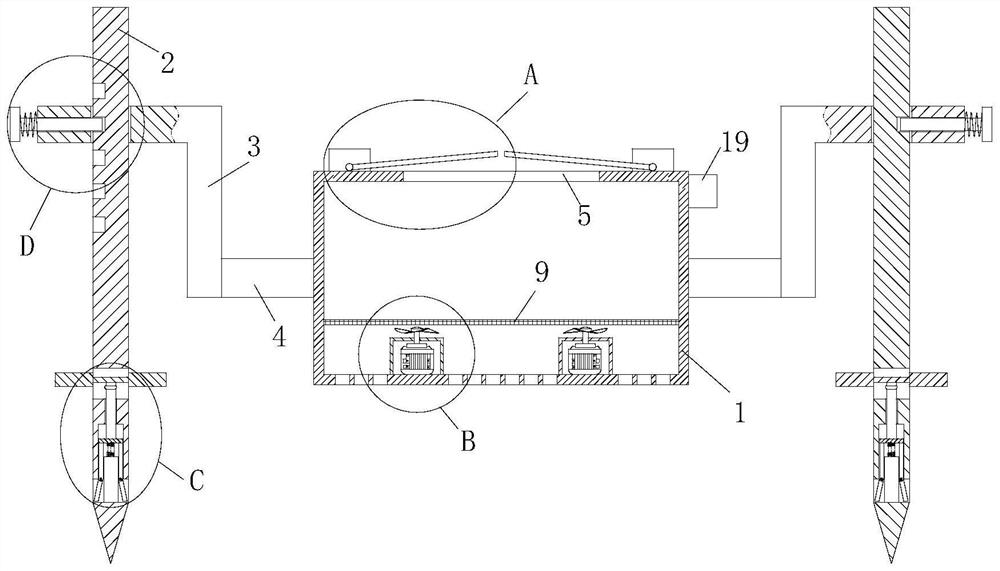
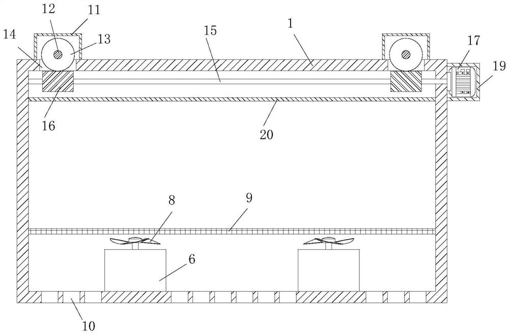
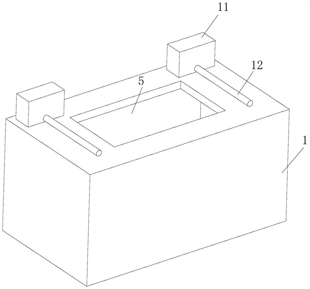
[0029] see Figure 1-7As shown, a water surface garbage collection device includes a collection box 1, a mounting rod 2, an L-shaped plate 3 and a connecting rod 4; the connecting rod 4 is fixed on the left and right sides of the collecting box 1; the L-shaped plate 3 Sleeved and slidably connected to the installation rod 2, and one end of the connection rod 4 is fixedly connected to one side of the L-shaped plate 3; the installation rod 2 is inserted on the ground; the top of the collection box 1 is provided with a feeding port 5. The bottom inner wall of the collection box 1 is fixed with a protective shell 6, the bottom inner wall of the collection box 1 is fixed with a turbine motor 7, and the turbine motor 7 is located inside the protective shell 6, and the turbine motor The output shaft of 7 is fixedly connected with turbine blade 8, and turbine blade 8 is positioned at the outside of protective shell 6; The inner wall of described collection box 1 is fixed with filter s...

Embodiment 2

[0038] see Figure 8 As shown, compared with Example 1, as another embodiment of the present invention, the opening of the third through groove 28 is fixed with elastic cloth 35, the second plate 29 penetrates through the elastic cloth 35, and the second rod 15 and the elastic cloth 35 are affixed; during work, through the elastic cloth 35, the third through groove 28 is in a closed state, which can prevent foreign matter from entering the third through groove 28, and then will not affect the normal sliding of the second plate 29, Also can not influence the normal sliding of push rod 27.

[0039] Working principle: Move the device to the downstream position of a small river, choose a position with a small river width, insert the installation pole 2 into the soil on both sides of the river, and then push the push plate 30 downward, so that the push plate 30 drives the second The plate 29 slides down along the third slot 28, and then the push rod 27 squeezes the No. 1 plate 22,...


PUM


Abstract

The invention relates to the technical field of garbage collection, in particular to a water surface garbage collection device which comprises a collection box, a mounting rod, an L-shaped plate and a connecting rod. The connecting rods are fixedly connected to the left side and the right side of the collecting box. The L-shaped plate sleeves the mounting rod and is in sliding connection with the mounting rod, and one end of the connecting rod is fixedly connected with one side of the L-shaped plate; the mounting rod is inserted into the ground; a feeding hole is formed in the top of the collecting box; a protective shell is fixedly connected to the inner side wall of the bottom of the collecting box, a turbine motor is fixedly connected to the inner side wall of the bottom of the collecting box and located in the protective shell, and turbine blades are fixedly connected to an output shaft of the turbine motor and located outside the protective shell; the inner wall of the collecting box is fixedly connected with a filter screen; and garbage floating on a river can enter the collecting box from the feeding opening in the top of the collecting box, manual garbage fishing is not needed, and manpower is saved.

Description

technical field [0001] The invention relates to the technical field of garbage collection, in particular to a water surface garbage collection device. Background technique [0002] In today's world, the problem of environmental pollution is becoming more and more serious. Among them, there is no lack of pollution in rivers. It is common to have garbage floating on rivers. [0003] For the garbage floating on the river surface, in the prior art, it is generally cleaned up by manual salvage. [0004] Obviously, manual salvage is time-consuming and labor-intensive, and requires a lot of time for the salvager. After a period of time, the salvager's work efficiency will be greatly reduced; therefore, a water surface garbage collection device is proposed to solve the above problems. Contents of the invention [0005] In order to make up for the deficiencies of the existing technology and solve the problem that manual salvage is time-consuming and labor-intensive, and consumes a...

Claims


Application Information

Patent Timeline
Patent Type & Authority Applications(China)
IPC IPC(8): E02B15/10
CPCE02B15/107
Inventor 侯海周文峰张芳耀徐智鄢军王善勇
Owner CREGC ARCHITECTURAL & CONSTR ENG CO LTD
Features
  • R&D
  • Intellectual Property
  • Life Sciences
  • Materials
  • Tech Scout
  • Unparalleled Data Quality
  • Higher Quality Content
  • 60% Fewer Hallucinations
Learn More