
Fabricated wallboard connecting mechanism based on fabricated building

A connecting mechanism and assembly technology, applied in building components, building structures, buildings, etc., can solve the problems of inconvenient installation and the inconvenient way of quasi-reserved pipe sockets, and achieve the effect of convenient and rapid installation and accelerated solidification. , the effect of improving stability

Pending Publication Date: 2022-03-18
HUBEI POLYTECHNIC UNIV
View PDF0 Cites 2 Cited by
  • Summary
  • Abstract
  • Description
  • Claims
  • Application Information

AI Technical Summary

Problems solved by technology

[0003] When installing prefabricated wall panels, it is often necessary to splice and fix multiple wall panels. The usual method is to reserve pipe fittings at the bottom of the installed wall panels. Leave the pipe on it, and then connect the two wallboards by pouring concrete, but in the actual assembly process, it is often not convenient to align the reserved pipe for socketing. A suitable plug-in mechanism is set on the surface between them, and the connection of the two wall panels is completed through horizontal insertion, but it needs to have a horizontal movement space in the extension direction of the wall to be installed during the installation process, and there is still inconvenient installation technical issues

Method used


Image

  • Fabricated wallboard connecting mechanism based on fabricated building
  • Fabricated wallboard connecting mechanism based on fabricated building
  • Fabricated wallboard connecting mechanism based on fabricated building

Examples


Embodiment 1

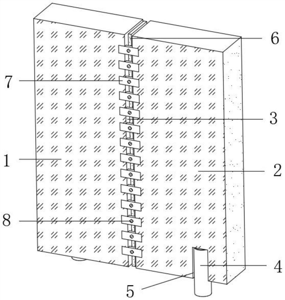
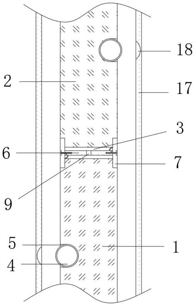
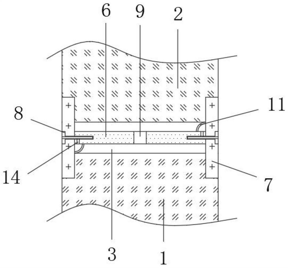
[0032] refer to Figure 1-Figure 7 , an assembly wall panel connection mechanism based on prefabricated buildings, including two sets of wall panels, embedded pipes 4 and a connection mechanism, the two sets of wall panels are respectively set as the first wall panel 1 and the second wall panel 2, and the first A gap cavity 3 is provided between the wall panel 1 and the second wall panel 2, and a connection mechanism that can be inserted horizontally is provided in the gap cavity 3, and concrete is poured in the gap cavity 3 after the connection mechanism is inserted, and the first wall panel 1 and the second wall panel The bottom end of the outer wall at the opposite end of the wallboard 2 is provided with a connecting groove 5, and the connecting groove 5 is compatible with the embedded pipe 4, and the two ends of the wallboard are provided with a panel 17 covering the embedded pipe 3. In actual use, from Move the two groups of wall panels in the panel direction of the wall ...

Embodiment 2

[0039] refer to figure 1 and Figure 8-Figure 9 , an assembly wall panel connection mechanism based on a prefabricated building, including two sets of wall panels, embedded pipes 4 and a connection mechanism, the two sets of wall panels are respectively set as the first wall panel 1 and the second wall panel 2, and the second A gap cavity 3 is provided between the first wall panel 1 and the second wall panel 2, and a connecting mechanism that can be inserted horizontally is arranged in the gap cavity 3, and concrete is poured in the gap cavity 3 after the connecting mechanism is inserted, the first wall panel 1 and the second wall panel The bottom end of the outer wall at the opposite end of the two wallboards 2 is provided with a connecting groove 5, and the connecting groove 5 is compatible with the embedded pipe 4, and the two ends of the wallboard are provided with a panel 17 covering the embedded pipe 3, and the connecting groove 5 is vertical. The inner side of the stra...

Embodiment 3

[0043] Embodiment 3 includes all structures and methods of embodiment 1 and implementation 2, with reference to Figure 1-Figure 10 , an assembly wall panel connection mechanism based on a prefabricated building, further includes an auxiliary groove 22 provided on the outer wall of one end of the limit block 20, and the bottom end of the auxiliary groove 22 is penetrated, and the auxiliary groove 22 is close to a side of the connection mechanism. The side inner wall is set as an inclined surface, and the side of the auxiliary groove 22 away from the connecting mechanism is set as a vertical surface, and the width of the auxiliary groove 22 gradually increases from top to bottom, so that the wallboard is first leaned against when the wallboard is connected and installed. Fix the connecting mechanism on the corresponding pre-embedded pipe 4, and then pour concrete from the top into the gap cavity 3, and then pour concrete into the pre-buried pipe 4 to the limit when the concrete ...


PUM


Abstract

The invention belongs to the technical field of fabricated buildings, in particular to a fabricated wallboard connecting mechanism based on a fabricated building, and provides the following scheme: the fabricated wallboard connecting mechanism comprises two groups of wallboards, an embedded pipe and a connecting mechanism, the two groups of wallboards are respectively set as a first wallboard and a second wallboard, and a gap cavity is formed between the first wallboard and the second wallboard; and a connecting mechanism capable of being horizontally inserted is arranged in the gap cavity, concrete is poured into the gap cavity after the connecting mechanism is inserted into the gap cavity, connecting grooves are formed in the bottom ends of the outer walls of the opposite ends of the first wall plate and the second wall plate correspondingly, and the connecting grooves are matched with the embedded pipes. The connecting grooves in the opposite end faces of the first wallboard and the second wallboard are embedded into the corresponding embedded pipes correspondingly, then the connecting mechanism is horizontally inserted into the gap cavity to be fixed, and then concrete is poured into the gap cavity so that the two sets of wallboards can be fixed to the connecting mechanism; therefore, the stability of the actually assembled wallboard is greatly improved while the wallboard is quickly assembled.

Description

technical field [0001] The invention relates to the technical field of prefabricated buildings, in particular to a connection mechanism for prefabricated wall panels based on prefabricated buildings. Background technique [0002] Buildings assembled from prefabricated components on the construction site are called prefabricated buildings, which mainly refer to the processing of a large number of building components outside the construction site to make finished products, and then send the components to the construction site for assembly. It is a modern industrialized production. representative of the way. [0003] When installing prefabricated wall panels, it is often necessary to splice and fix multiple wall panels. The usual method is to reserve pipe fittings at the bottom of the installed wall panels. Leave the pipe on, and then connect the two wall panels by pouring concrete. However, in the actual assembly process, it is often not convenient to align the reserved pipe ...

Claims


Application Information

Patent Timeline
IPC IPC(8): E04B1/04E04B2/00E04B1/61E04B1/41
CPCE04B1/043E04B2/00E04B1/61E04B1/41E04B1/4157E04B1/4114E04B1/612
Inventor 刘西京易国庆
Owner HUBEI POLYTECHNIC UNIV
Learn More