
Missile folding rudder self-locking system

A folding rudder, self-locking technology, applied to projectiles, offensive equipment, weapon types, etc., can solve the problems of rising structural temperature, inability to lock the folding rudder in place, and inability to unfold the folding rudder surface in place, achieving a simple structure and high technology. Practical effect

Pending Publication Date: 2022-03-18
SHANGHAI INST OF ELECTROMECHANICAL ENG
View PDF9 Cites 1 Cited by
  • Summary
  • Abstract
  • Description
  • Claims
  • Application Information

AI Technical Summary

Problems solved by technology

However, the technology adopted above has the following disadvantages. During the long-term flight of the missile, the structural temperature of the spring in the folding rudder, which plays the role of locking the outer rudder, will increase. After the stiffness of the spring decreases, after the pin puller is unlocked, the folding rudder The surface does not expand into place under the action of the spring and cannot actually lock the folded rudder in place
[0004] Therefore, at present, there is no effective folding rudder system that can be used for long-term high Mach number cruise flight missiles in adjacent space

Method used


Image

  • Missile folding rudder self-locking system
  • Missile folding rudder self-locking system
  • Missile folding rudder self-locking system

Examples


Embodiment Construction

[0026] The present invention will be described in detail below in conjunction with specific embodiments. The following examples will help those skilled in the art to further understand the present invention, but do not limit the present invention in any form. It should be noted that those skilled in the art can make several changes and improvements without departing from the concept of the present invention. These all belong to the protection scope of the present invention.

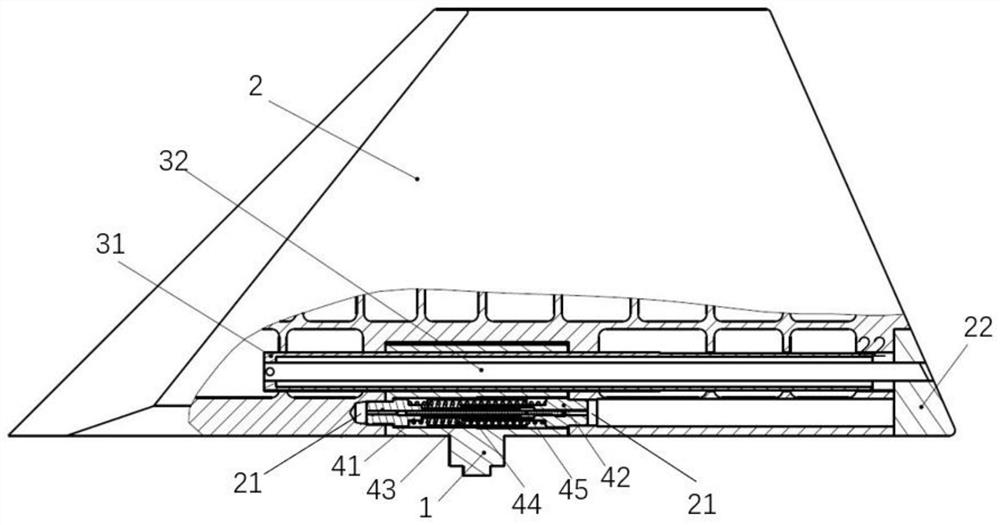
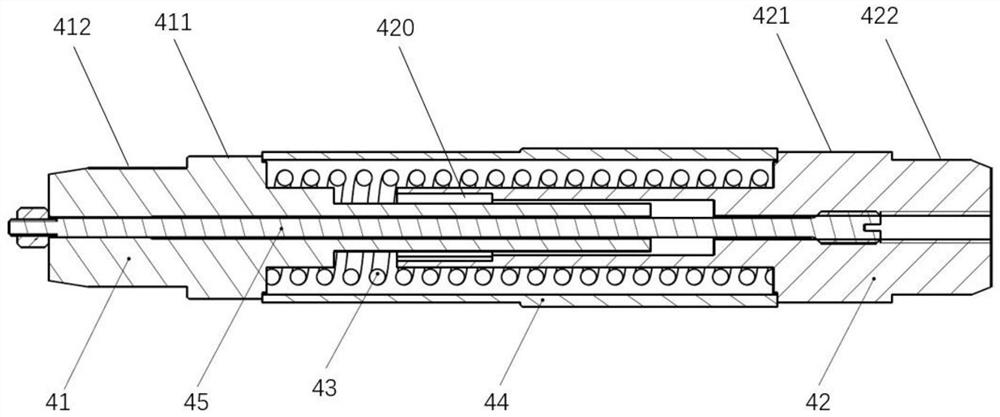
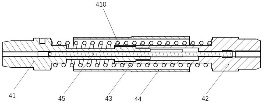
[0027] The invention provides a missile folding rudder self-locking system, which includes an inner rudder 1, an outer rudder 2, a driving mechanism 3 that drives the outer rudder 2 to rotate and unfold relative to the inner rudder 1, and a lock that locks the inner rudder 1 and the outer rudder 2 pin mechanism4. The inner rudder 1 and the outer rudder 2 are driven and connected by a drive mechanism 3. Preferably, the drive mechanism 3 is mainly composed of a rotating shaft sleeve 31 and a torsion bar 3...


PUM


Abstract

The invention relates to a missile folding rudder self-locking system in the technical field of missile equipment. The missile folding rudder self-locking system comprises an inner rudder, an outer rudder, a driving mechanism and a lock pin mechanism. The outer rudder is provided with a lock hole, the lock pin mechanism comprises a first lock rod, a second lock rod, a torsional spring and a lock pin sleeve, the lock pin sleeve is fixed on the inner rudder, the torsional spring is sleeved in the lock pin sleeve, and the first lock rod and the second lock rod are respectively inserted from two ends of the torsional spring and pre-press the torsional spring; the inner rudder and the outer rudder are in driving connection through the driving mechanism, in the process that the driving mechanism drives the outer rudder to be unfolded relative to the inner rudder, the torsion spring pushes the first locking rod and the second locking rod to be axially separated, and after the outer rudder and the inner rudder are unfolded in place, the end of the first locking rod and the end of the second locking rod are embedded into the locking holes correspondingly. The end of the first locking rod and the end of the second locking rod are used for preventing the inner rudder and the outer rudder from rotating in the radial direction. The missile folding rudder is simple in structure, high in process practicability, short in machining period and suitable for working in a high-temperature environment for a long time.

Description

technical field [0001] The invention relates to the technical field of missile equipment, in particular to a missile folding rudder self-locking system. Background technique [0002] With the continuous innovation and development of the missile power system, the long-term high Mach number cruise flight of the missile in the adjacent space has become a reality. During long-term high-speed cruising flight, the missile faces serious aerodynamic heating problems, and the thermal environment of its air rudder will be even harsher. Missiles launched from ships require their air rudders to adopt the form of folded outer rudders to minimize the maximum outer envelope of the missiles to adapt to the ship's launch. During the long-term flight of the missile, the structural temperature of the spring in the folding rudder, which plays the role of locking the outer rudder, will increase, resulting in a decrease in its stiffness, which will cause a decrease in the axial locking force pro...

Claims


Application Information

Patent Timeline
Patent Type & Authority Applications(China)
IPC IPC(8): F42B10/64F42B10/14
CPCF42B10/64F42B10/14
Inventor 李宗阳许自然任智毅窦怡彬李煜陆云超刘陆广程广益涂静江玉刚
Owner SHANGHAI INST OF ELECTROMECHANICAL ENG
Learn More