Noise monitoring device for environmental monitoring
A noise monitoring and environmental monitoring technology, which is applied in measuring devices, measuring ultrasonic/sonic/infrasonic waves, instruments, etc., can solve the problems of limited application environment, lack of lifting function of noise monitoring devices, dust on the surface of the display screen, etc., to improve the application range effect
- Summary
- Abstract
- Description
- Claims
- Application Information
AI Technical Summary
Problems solved by technology
Method used
Image

Examples
Embodiment 1
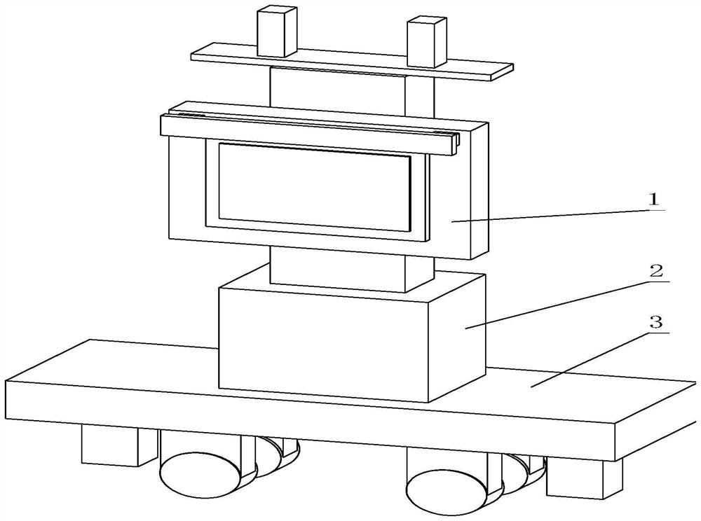
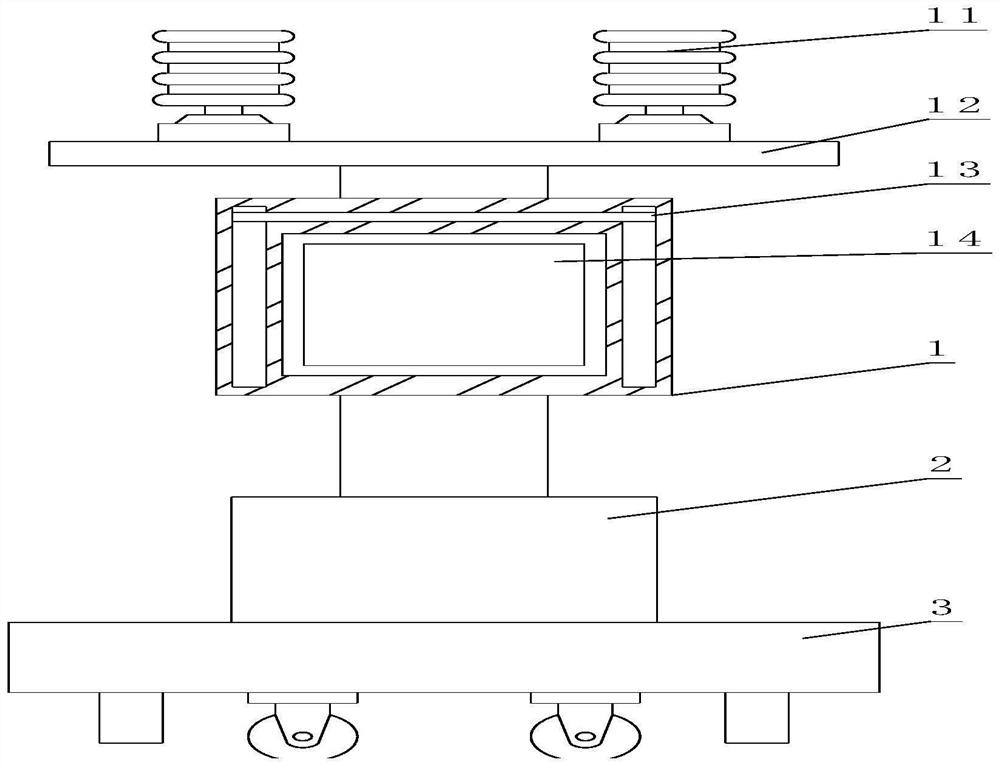
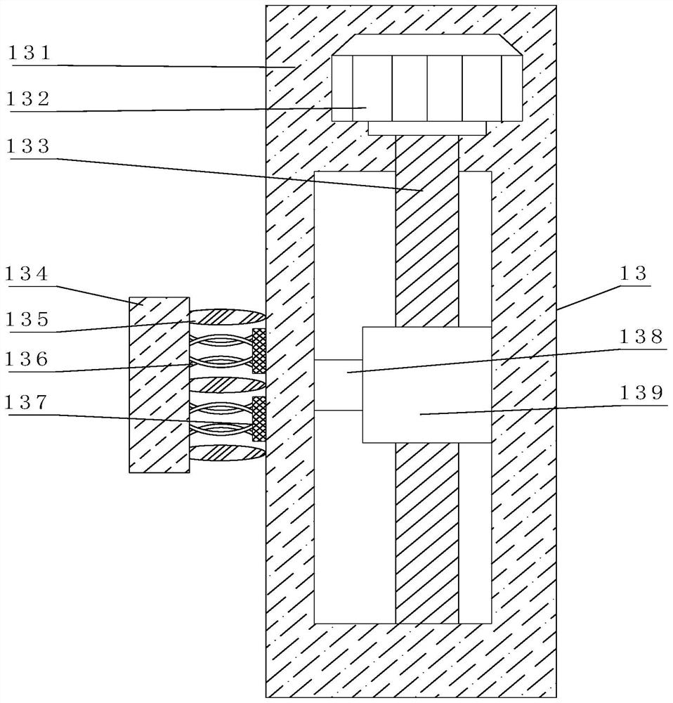
[0040] Such as Figure 1-6As shown, the present invention provides a noise monitoring device for environmental monitoring, including a noise monitoring device 1, the bottom of the noise monitoring device 1 is provided with a lifting mechanism 2, and the bottom of the lifting mechanism 2 is provided with a displacement mechanism 3, and the noise monitoring device 1 includes Cleaning mechanism 13, cleaning mechanism 13 comprises cleaning shell 131, and the inside of cleaning shell 131 is provided with motor 132, and the inside of cleaning shell 131 is provided with chute, and the output end of motor 132 is fixedly connected with rotating threaded rod 133, and the rotating threaded rod 133 The bottom is movably connected with the bottom of the inner wall of the chute, the surface of the rotating threaded rod 133 is threaded and connected with a threaded ring block 139 inside the chute, the front of the threaded ring block 139 is fixedly connected with a connecting rod 138, and the...
Embodiment 2
[0043] Such as Figure 1-6 As shown, on the basis of Embodiment 1, the present invention provides a technical solution: preferably, the lifting mechanism 2 includes a lifting shell 21, the bottom of the inner wall of the lifting shell 21 is movably connected with a movable threaded rod 22, and the surface of the movable threaded rod 22 A No. 1 bevel gear 26 is fixedly connected, and No. 2 bevel gear 27 meshes with the surface of the No. 1 bevel gear 26. One side of the No. 2 bevel gear 27 is fixedly connected with a double-headed motor 28, and the double-headed motor 28 is arranged on the inner wall of the lifting shell 21. At the bottom, the surface of the movable threaded rod 22 and the top of the No. 1 bevel gear 26 are provided with a baffle 29, the side of the baffle 29 is fixedly connected with the inner wall side of the lifting shell 21, and the top of the baffle 29 is fixedly connected with an elastic pad 24, The top of baffle plate 29 is fixedly connected with spring ...
Embodiment 3
[0046] Such as Figure 1-6 As shown, on the basis of Embodiment 1, the present invention provides a technical solution: preferably, the displacement mechanism 3 includes a fixed casing 42, and a groove is opened inside the fixed casing 42, and an electric push rod is arranged on the top of the inner wall of the groove 31, the bottom of the electric push rod 31 is fixedly connected with the No. 2 lifting plate 32, the side of the No. 2 lifting plate 32 is movably connected with the inner wall side of the groove, and the bottom of the No. 2 lifting plate 32 is fixedly connected with the fixed rod 34, and the fixed rod 34 The inside of the hole is provided with an opening, the inner wall of the opening is provided with an electromagnet 40, the inner wall of the opening is fixedly connected with an elastic piece 41, the inside of the elastic piece 41 is fixedly connected with a limit rod 37, and the two ends of the limit rod 37 extend to the elastic Outside the sheet 41, one end o...
PUM
 Abstract
Description
Claims
Application Information
 - R&D Engineer
- R&D Manager
- IP Professional
- Industry Leading Data Capabilities
- Powerful AI technology
- Patent DNA Extraction
Browse by: Latest US Patents, China's latest patents, Technical Efficacy Thesaurus, Application Domain, Technology Topic.
© 2024 PatSnap. All rights reserved.Legal|Privacy policy|Modern Slavery Act Transparency Statement|Sitemap