Battery protection circuit, battery assembly and electronic cigarette
A technology for protecting circuits and electronic cigarettes, applied in the direction of tobacco, etc., can solve the problems of single function of electronic cigarettes, exhausted batteries, and consumption of battery power, etc., to improve the user experience, increase the duration of use, and reduce power consumption.
- Summary
- Abstract
- Description
- Claims
- Application Information
AI Technical Summary
Problems solved by technology
Method used
Image
Examples
no. 1 example
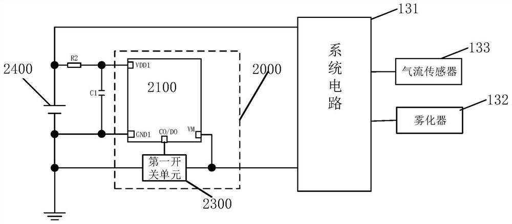
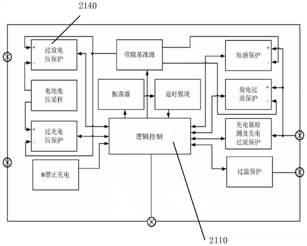
[0088] In this example, see figure 1 , figure 2 , the electronic cigarette 100 is a conventional electronic cigarette, and its cartridge 120 is a replaceable cartridge. When the cartridge 120 is used up, the user can remove the old cartridge 120 and replace it with a new cartridge 120; The battery 2400 is a rechargeable battery 2400, such as a lithium battery, a nickel-cadmium battery, a nickel-metal hydride battery, etc. The device 110 includes a charging interface, which is electrically connected to the battery 2400 via the battery protection circuit 2000, and the charging interface is used for charging with an external connection. For example, the charger can provide voltage and current of 5V / 1A or 5V / 2A to charge the battery 2400 . When the power of the battery 2400 in the electronic cigarette is low, the user can connect the charger through the charging interface to charge the battery 2400 . Since the cartridge 120 is a replaceable cigarette, the cigarette rod 110 is a...
no. 2 example
[0129] see Figure 13 , Figure 13 It is the circuit block diagram of the electronic device of the second embodiment of the present application. This embodiment is similar to the first embodiment. Therefore, the parts not described in this embodiment can refer to the first embodiment. The main points of this embodiment and the first embodiment The difference is that the first switch unit 2300 is placed outside and the first switch unit 2300 is placed above.
[0130] See Figure 13 , in this embodiment, the first switch unit 2300 is placed outside and the first switch unit 2300 is placed above, that is, the first switch unit 2300 is located outside the battery protection module 2100 . The first terminal of the first switch unit 2300 is electrically connected to the positive pole of the battery 2400, the second terminal of the first switch unit 2300 is electrically connected to the system terminal VM and the system circuit 131 respectively, and the control terminal of the firs...
no. 3 example
[0135] see Figure 14 , Figure 14 It is the circuit block diagram of the electronic device of the third embodiment of the present application. This embodiment is similar to the first and second embodiments. Therefore, the parts not described in this embodiment can refer to the previous embodiments. This embodiment is similar to the first and second embodiments. The main difference between the two embodiments is that the battery protection module 2100 further includes a first shipping outlet QC1.
[0136] Please refer to Figure 14 and Figure 15 , in this embodiment, the second shipping exit QC2 is not directly connected to the system VM. Specifically, the battery protection module 2100 also includes a first shipping exit terminal QC1, the first shipping exit terminal QC1 is electrically connected to the second shipping exit terminal QC2, and the first shipping exit terminal QC1 is connected to the terminal of the first NOT gate 2121. Input terminal, the output terminal o...
PUM
 Abstract
Description
Claims
Application Information
 - R&D
- Intellectual Property
- Life Sciences
- Materials
- Tech Scout
- Unparalleled Data Quality
- Higher Quality Content
- 60% Fewer Hallucinations
Browse by: Latest US Patents, China's latest patents, Technical Efficacy Thesaurus, Application Domain, Technology Topic, Popular Technical Reports.
© 2025 PatSnap. All rights reserved.Legal|Privacy policy|Modern Slavery Act Transparency Statement|Sitemap|About US| Contact US: help@patsnap.com


