Intelligent shoe cabinet with disinfection function based on intelligent home

A smart home, functional technology, used in home appliances, furniture parts, cabinets, etc., can solve problems such as poor experience

Active Publication Date: 2022-03-22
江苏伟森家居有限公司
View PDF7 Cites 1 Cited by
  • Summary
  • Abstract
  • Description
  • Claims
  • Application Information

AI Technical Summary

Problems solved by technology

[0005] In order to overcome the shortcomings that the shoes placed at the bottom of the shoe cabinet need to bend over when taking and placing them, and the experience effect is not good for people who are tired from work, the purpose of the present invention is to provide a smart home with disinfection function. Shoebox

Method used


Image

  • Intelligent shoe cabinet with disinfection function based on intelligent home
  • Intelligent shoe cabinet with disinfection function based on intelligent home
  • Intelligent shoe cabinet with disinfection function based on intelligent home

Examples


Embodiment 1

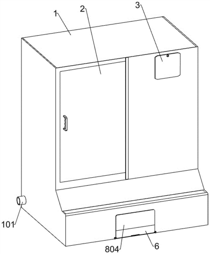
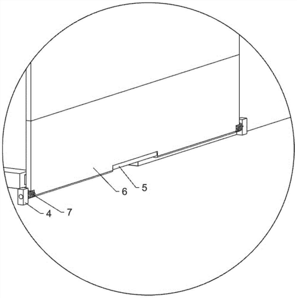
[0036] A smart shoe cabinet with disinfection function based on smart home, such as Figure 1-15 As shown, it includes a casing 1, an air outlet pipe 101, a sliding door 2, a control panel 3, a fixed block 4, a first fixed rod 5, a square rotating plate 6, a first torsion spring 7, a shoe-removing mechanism, a transmission mechanism, and a placement mechanism. Mechanism and storage mechanism, the left side of the casing 1 is embedded with an air outlet pipe 101, the left side of the front side of the casing 1 is slidably connected with the sliding door 2, the right side of the front side of the casing 1 is fixedly connected with the control panel 3, the The lower part of the front side is provided with a square through hole, and the left and right sides of the square through hole on the front side of the housing 1 are fixedly connected with a fixed block 4, and a first fixed rod 5 is fixedly connected between the two fixed blocks 4, and on the first fixed rod 5 The rotation is...

Embodiment 2

[0039] On the basis of Example 1, such as Figure 4-15As shown, the shoe removal mechanism includes a first bottom plate 801, a first side support plate 802, a first electric slide rail 803, a cover plate 804, a rear support plate 805, a first support plate 806, a second support plate 807, a second Electric slide rail 809, support rod 810, spline sliding rod 811, arc-shaped fixed plate 812, first spring 813, rotating shaft 814, arc-shaped rotating plate 815, second torsion spring 816, rubber wheel 817, infrared monitoring module 818, Support frame 820, first servo motor 821, threaded rod 822, threaded plate 823, first connecting rod 824, turret 825, first electric wheel 826, third electric slide rail 827, second servo motor 828, second fixed Rod 829, third support plate 830, fixed frame 831 and elastic rubber sheet 832, the first bottom plate 801 is slidably connected in the square through hole of the shell 1, the first bottom plate 801 is slidably connected with the lower par...

Embodiment 3

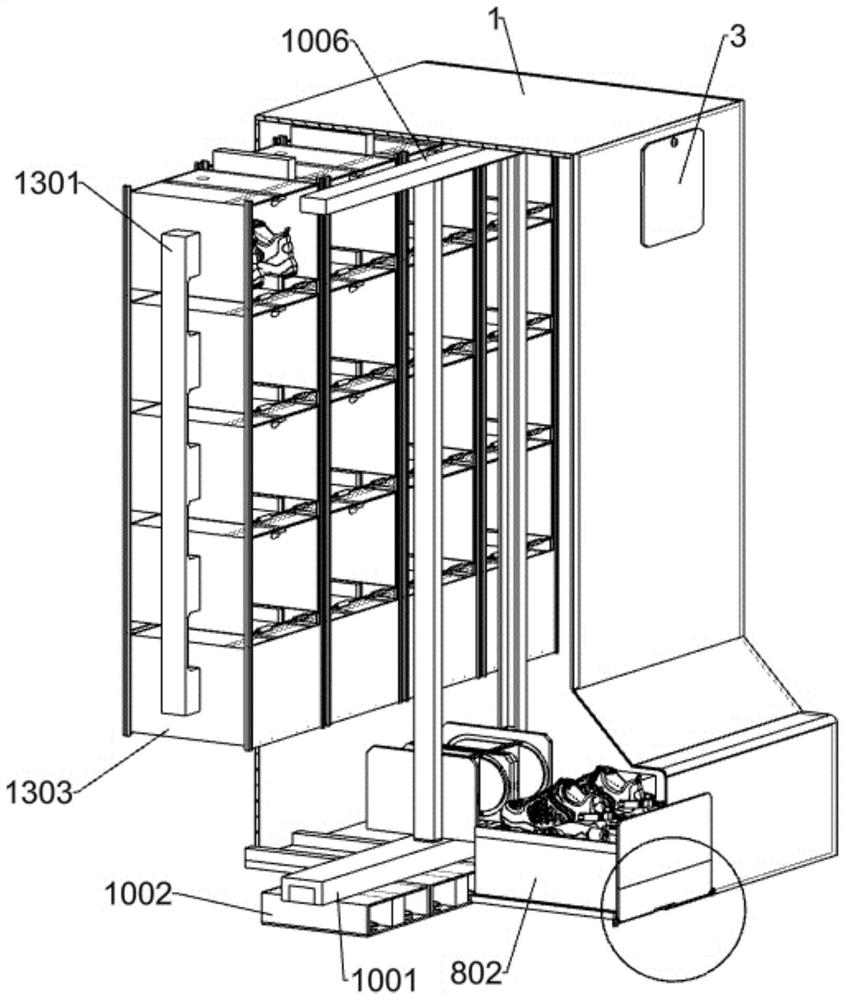
[0051]On the basis of Embodiment 1, when the user is going to wear shoes to go out, then the user selects the shoes he wants to wear on the touch screen of the control panel 3, and then the control panel 3 starts the fifth electric slide rail 1006 and the sixth electric slide rail 1007, through the cooperation of the fifth electric slide rail 1006 and the sixth electric slide rail 1007, the second bottom plate 1009 and the parts on it are driven to cooperate with the third square shell 1303 with shoes, and then the above operation is repeated to move the swing plate 1015 to The upper part of the second side support plate 1008 is parallel to the second bottom plate 1009, then the control panel 3 starts the seventh electric slide rail 1304, and the electric slider of the seventh electric slide rail 1304 drives the sliding frame 1305 and the second plastic baffle plate 1306 to Slide forward, and the control panel 3 activates the fifth electric wheel 1308 at the same time, the fift...


PUM


Abstract

The invention relates to the field of smart home, in particular to a smart shoe cabinet with a disinfection function based on smart home. The shoe cabinet aims at solving the problem that people who work tired need to bend down to take and place shoes placed at the lowest portion of the shoe cabinet, and the experience effect is not good for people who work tired. According to the technical scheme, the intelligent shoe cabinet with the disinfection function based on the intelligent home comprises a shell, a shoe taking-off mechanism and a conveying mechanism; the shoe taking-off mechanism is arranged in the square through hole of the shell, and the conveying mechanism is arranged on the lower side of the shoe taking-off mechanism. By arranging the shoe taking-off mechanism, a user is prevented from stooping to take off shoes, slipping is avoided when the user takes off the shoes through a clamping assembly arranged on the slipper mechanism, and inconvenience caused to the user due to the fact that the shoes slip to be separated from the upper side face of a second supporting plate when the user takes off the shoes is avoided through a stabilizing assembly arranged on the slipper mechanism. By arranging the conveying mechanism, slipping is avoided when the user takes off the shoes.

Description

technical field [0001] The invention relates to the field of smart home, in particular to a smart shoe cabinet with disinfection function based on smart home. Background technique [0002] The traditional shoe cabinet is the most commonly used shoe cabinet in the home. Its main purpose is to display idle shoes. At the same time, the continuous changes and innovations in style enable it to match the shoe cabinet with different home environments. In this way, the shoe cabinet can store shoes and The two-way effect of decoration, smart shoe cabinet refers to a new shoe cabinet with many functions added on the basis of traditional ordinary shoe cabinet, which integrates novelty, technology, health and intelligence. [0003] In the existing technology, it is still necessary to place the removed shoes in the shoe cabinet, then put the shoes in the shoe cabinet for disinfection, and then take out the slippers from the shoe cabinet for replacement, especially the ones placed at the ...

Claims


Application Information

Patent Timeline
Patent Type & Authority Applications(China)
IPC IPC(8): A47B61/04A47B97/00A47G25/80A47L23/20A61L2/10A61L2/18
CPCA47B61/04A47B97/00A47G25/80A47L23/20A61L2/10A61L2/18Y02P90/02
Inventor 李伟李浩
Owner 江苏伟森家居有限公司
Why Eureka
Try Eureka