Hidden machine tool cross beam structure with adjustable precision

A concealed and adjustable technology, applied in the field of machine tools, can solve problems such as limited strength and achieve the effect of improving strength

Pending Publication Date: 2022-03-22
DEQING TIANMA BEARING CO LTD
View PDF1 Cites 1 Cited by
  • Summary
  • Abstract
  • Description
  • Claims
  • Application Information

AI Technical Summary

Problems solved by technology

The welded beam of this patent is combined with the longitudinal rib plate, X-shaped rib plate and the rectangular beam frame to form an overall fully welded structure, which has good overall rigidity, good stability and is not easy to deform, but only through the rib plate. Reinforcement is obviously limited in strength

Method used


Image

  • Hidden machine tool cross beam structure with adjustable precision
  • Hidden machine tool cross beam structure with adjustable precision
  • Hidden machine tool cross beam structure with adjustable precision

Examples


Embodiment Construction

[0026] The following specific examples are only explanations of the present invention, and it is not a limitation of the present invention. Those skilled in the art can make modifications without creative contribution to the present embodiment as required after reading this specification, but as long as they are within the rights of the present invention All claims are protected by patent law.

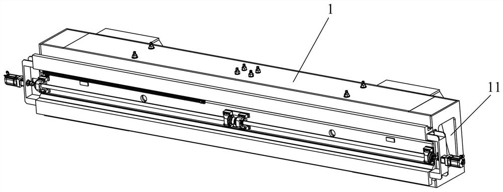
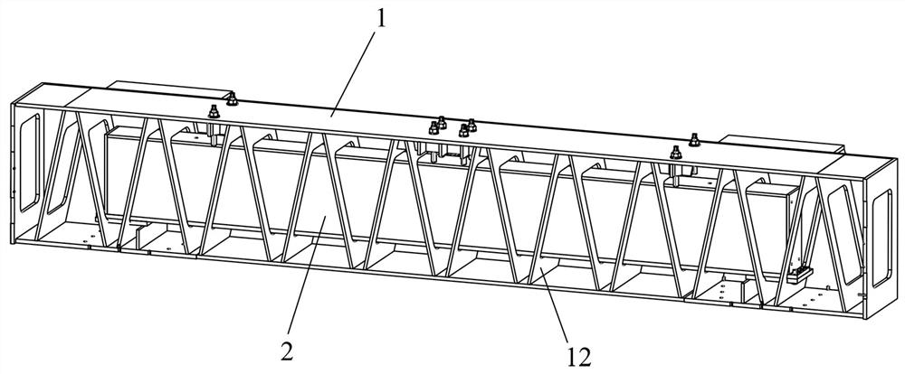
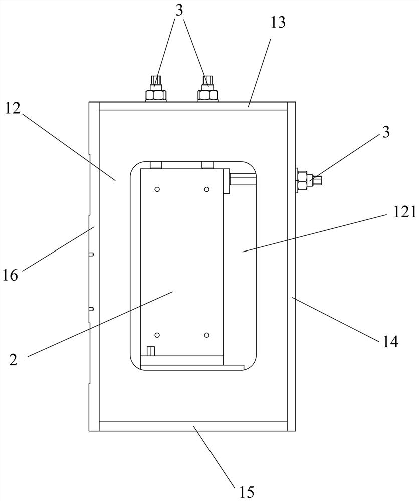
[0027] A precision-adjustable concealed machine tool crossbeam structure of the present invention includes an outer crossbeam frame 1 and an inner crossbeam 2 extending laterally from left to right. When in use, guide rails are usually fixed on the front side of the outer crossbeam frame 1, and then The tool holder is installed on the guide rail for use. At this time, the gravity of the tool holder and the guide rail and other components acts on the outer beam frame 1, and the left and right ends of the outer beam frame 1 are usually erected on the feet, which can be supported by the fe...


PUM


Abstract

The invention relates to the technical field of machine tools, in particular to a precision-adjustable hidden machine tool cross beam structure which comprises an outer cross beam frame and an inner cross beam which extend in the left-right transverse direction, an annular rib plate is arranged in a first cavity in the outer cross beam frame, a center hole is defined by the inner edge of the annular rib plate, and the outer edge of the annular rib plate is fixedly connected with the outer cross beam frame. The inner cross beam is located in the first cavity, penetrates through the center hole and is erected on the annular rib plate, and the inner cross beam is fixedly connected with the annular rib plate or the outer cross beam frame body; the outer cross beam frame body comprises a first rear supporting plate and a first upper supporting plate, the inner cross beam comprises a rear supporting face and an upper supporting face, and precision adjusting bolts are arranged on the first rear supporting plate and the first upper supporting plate in a penetrating mode. The precision adjusting bolt can adjust the distance between the first rear supporting plate and the rear supporting face and the distance between the first upper supporting plate and the upper supporting face, and the first rear supporting plate and the first upper supporting plate are each provided with an installation hole for the precision adjusting bolt to penetrate through.

Description

technical field [0001] The invention relates to the technical field of machine tools, in particular to a concealed machine tool beam structure with adjustable precision. Background technique [0002] Existing numerically controlled machine tools such as milling machines, boring machines, and lathes are relatively bulky, requiring beams as load-bearing parts to install other heavier guide rails, spindles and other components. Most of the beams of the machine tools are integrally formed castings. The tool holders of the machine tools can also move back and forth along the X-axis direction under the guidance of the beams. However, due to the large span of the beams and the heavy weight of the tool holders and beams , it will lead to deformation of the beam, which will affect the radial runout of the processed workpiece, and then affect the processing quality of the processed workpiece. Therefore, the existing machine tool beams are usually equipped with reinforcement structure...

Claims


Application Information

Patent Timeline
Patent Type & Authority Applications(China)
IPC IPC(8): B23Q1/01
CPCB23Q1/015
Inventor 马兴法吴敏
Owner DEQING TIANMA BEARING CO LTD
Why Eureka
Try Eureka