Automatic resistance wire burying equipment for PE pipe fitting and wiring method of automatic resistance wire burying equipment
A technique of embedding resistors and pipe fittings, which is applied in the field of automatic PE pipe embedding resistance wire equipment and its wiring, can solve the problems of unusable PE pipe fittings, mold core damage to the injection molding shape, poor cooling effect, etc., and achieve good cooling, accelerated cooling, and reduced cooling. The effect of small speed
- Summary
- Abstract
- Description
- Claims
- Application Information
AI Technical Summary
Problems solved by technology
Method used
Image
Examples
Embodiment 1
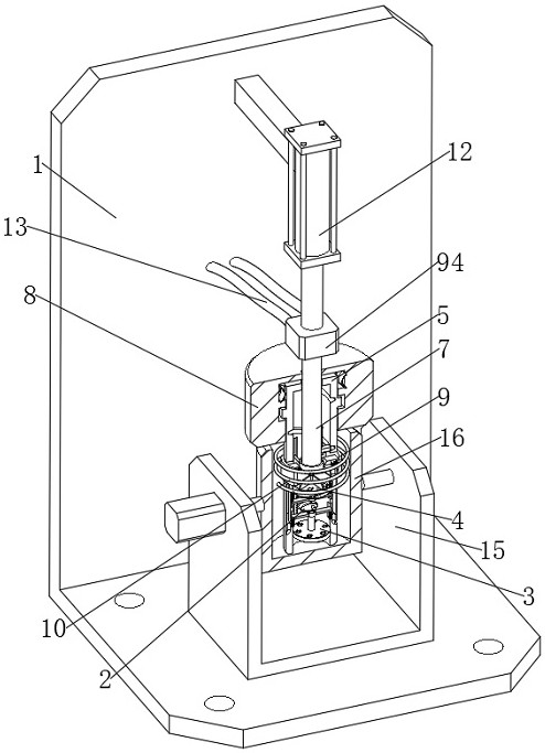
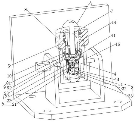
[0040] see Figure 1-3 , a kind of equipment for automatically embedding resistance wires for PE pipe fittings, including a base 1 and a support frame 15 on the base 1, a mold 16 is rotatably connected to the support frame 15, and a mold core 5 is slidingly connected to the inside of the mold 16, and the upper slide of the mold core 5 A support device 9 is connected, the outer surface of the support device 9 is provided with a resistance wire 10, the support device 9 is used to support the resistance wire 10, and an adjustment rod 7 is installed inside the mold core 5, and the adjustment rod 7 is used to interfere with the support device 9;
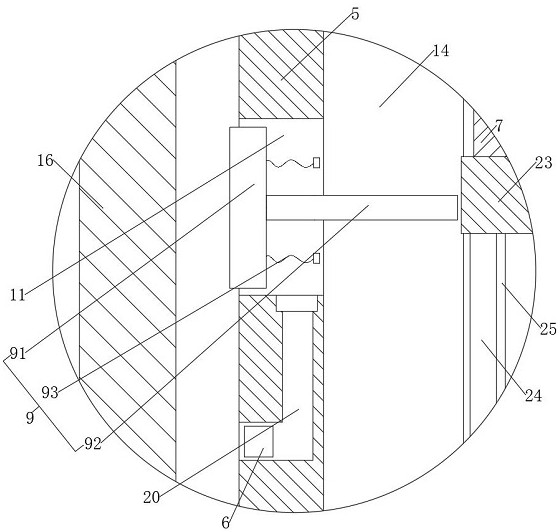
[0041] The mold core 5 is provided with a receiving groove 11, and the supporting device 9 is slidably connected to the inside of the receiving groove 11. The supporting device 9 includes an arc-shaped plate 91 slidably connected to the inside of the receiving groove 11. The arc-shaped plate 91 is used to resist the resistance wire 10 , a...
Embodiment 2
[0046] This embodiment is an improvement made on the basis of Embodiment 1, according to Figure 1-4 As shown, the inside of the mold core 5 is provided with a piston cavity 14, the adjusting rod 7 is slidably connected to the inside of the piston cavity 14, and the inside of the piston cavity 14 is also slidably connected to a suction part 3, which is used to extract the inside of the mold 16. The inside of the piston cavity 14 is also rotatably connected with the driving part 2, the driving part 2 is used to drive the suction part 3 to slide, the suction part 3 includes the third spring 38 installed on the inner wall of the mold core 5, on the third spring 38 A first horizontal plate 37 is installed, and a first slide bar 32 is installed on the first horizontal plate 37. The driving part 2 is used to drive the first slide bar 32 to slide. The first piston 31, the first piston 31 is provided with a first one-way ventilation part, the first one-way ventilation part is used to ...
Embodiment 3
[0053] This embodiment is an improvement made on the basis of Embodiment 2, according to Figure 1-6 As shown, the inside of the mold core 5 is also equipped with an exhaust component 4, the exhaust component 4 is used to exhaust the air extracted by the first piston 31 to the inside of the mold 16, and the exhaust component 4 includes a valve that is slidably connected to the inside of the mold core 5. The second slide bar 49, the second slide bar 49 is in contact with the drive part 2, the drive part 2 is used to drive the second slide bar 49 to slide, the second slide bar 49 is equipped with a second piston 45, and the second piston 45 is used for The air inside the mold core 5 is extracted, the second piston 45 is provided with a second one-way ventilation part 46, the structure of the second one-way ventilation part 46 is exactly the same as that of the second one-way ventilation part, and the inside of the mold core 5 is also provided with The air storage bin 20 is used ...
PUM
 Abstract
Description
Claims
Application Information
 - R&D
- Intellectual Property
- Life Sciences
- Materials
- Tech Scout
- Unparalleled Data Quality
- Higher Quality Content
- 60% Fewer Hallucinations
Browse by: Latest US Patents, China's latest patents, Technical Efficacy Thesaurus, Application Domain, Technology Topic, Popular Technical Reports.
© 2025 PatSnap. All rights reserved.Legal|Privacy policy|Modern Slavery Act Transparency Statement|Sitemap|About US| Contact US: help@patsnap.com


