
Ground unmanned platform test system

An unmanned platform and test system technology, which is applied in the direction of motor vehicles, tracked vehicles, transportation and packaging, etc., can solve the problems of armored vehicles and ground unmanned platform test systems, such as damage, difficulty in achieving both effects, locking and fixing, etc. Achieve the effects of avoiding impact damage, improving stability, and increasing movement speed

Active Publication Date: 2022-03-22
ARMOR ACADEMY OF CHINESE PEOPLES LIBERATION ARMY
View PDF7 Cites 1 Cited by
  • Summary
  • Abstract
  • Description
  • Claims
  • Application Information

AI Technical Summary

Problems solved by technology

[0003] Most of the currently used ground unmanned platform test systems use a single walking mode, resulting in wheeled ground unmanned platform test systems that are more stable when walking on uneven roads but faster when walking on flat roads, or crawler-type The walking ground unmanned platform test system is stable when walking on uneven roads, but the speed is slow when walking on flat roads, and it is difficult to achieve the best of both worlds; the ground unmanned platform test system can also be used to transport armored vehicles, but the currently used The ground unmanned platform test system only plays the role of limiting the position of the armored vehicle, and does not lock and fix the armored vehicle and the ground unmanned platform test system, which causes the armored vehicle to shake easily due to bumps or inertia during transportation. During the shaking process, there is a collision with the ground unmanned platform test system, which may easily cause damage to the armored vehicle and the ground unmanned platform test system

Method used


Image

  • Ground unmanned platform test system
  • Ground unmanned platform test system
  • Ground unmanned platform test system

Examples


Embodiment Construction

[0030] The embodiments of the present invention will be described in detail below with reference to the accompanying drawings, but the present invention can be implemented in many different ways defined and covered by the claims.

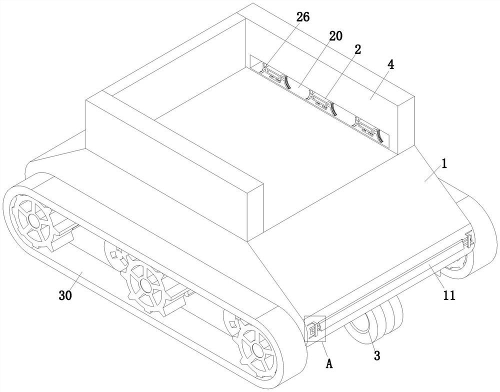
[0031] refer to figure 1 , a ground unmanned platform test system, comprising a vehicle body 1, a moving mechanism 3 and a side baffle 4, the vehicle body 1 is equipped with a moving mechanism 3, and the upper end surface of the vehicle body 1 is equipped with a side baffle 4 of a 匚-shaped structure, A locking mechanism 2 is provided on the side baffle 4 .

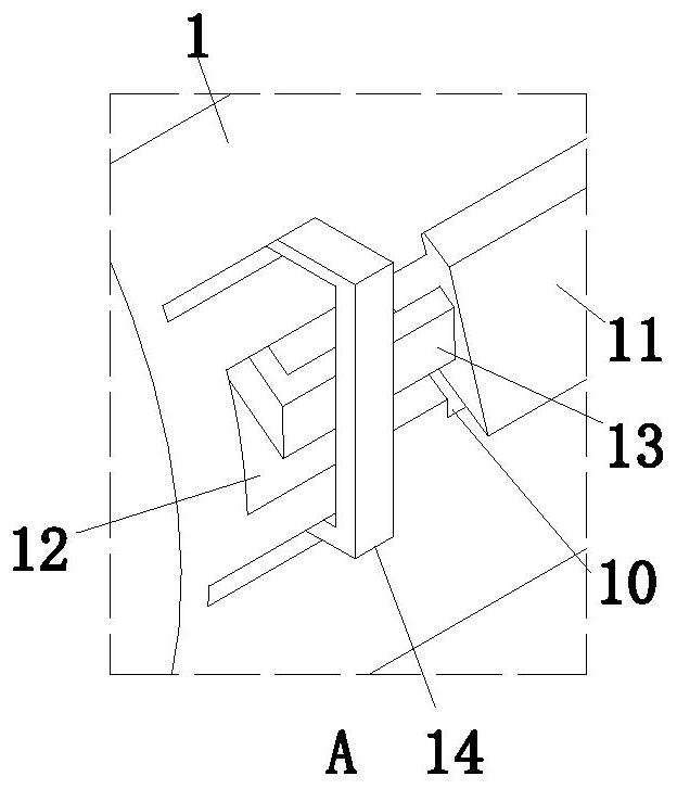
[0032] refer to figure 2The left side of the vehicle body 1 is provided with a stepped groove 10, and a transition plate 11 is slidably connected to the stepped groove 10. The end of the stepped groove 10 close to the side wall of the vehicle body 1 is provided with a handle groove 12 symmetrically arranged front and rear, and the transition plate 11 is equipped with drag handle 13 which is s...


PUM


Abstract

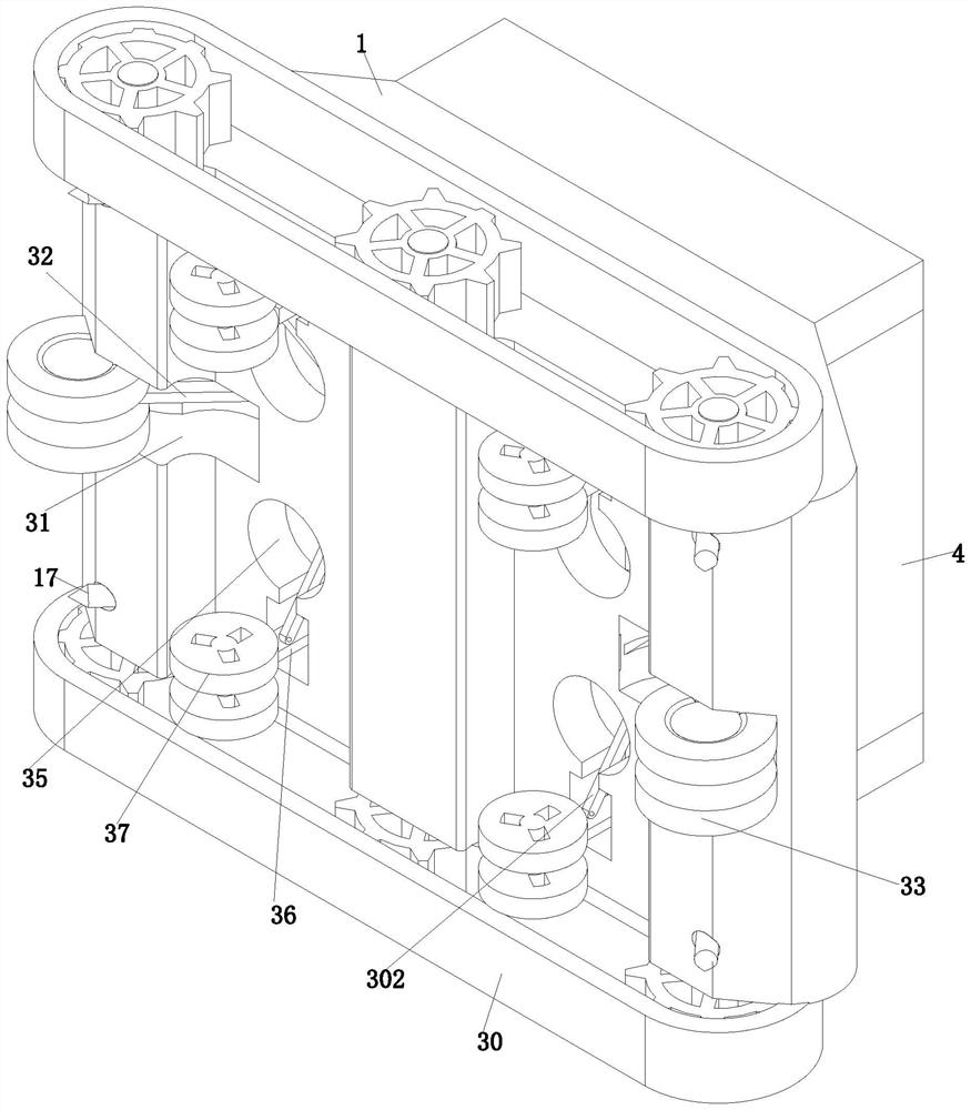
The invention relates to the technical field of ground unmanned platforms, in particular to a ground unmanned platform test system which comprises a vehicle body, a moving mechanism and side baffles. According to the ground unmanned platform test system, a crawler-type walking mode and a wheel-type walking mode can be freely converted through the moving mechanism, so that the vehicle body can be freely converted into a relatively convenient walking mode between a flat road section and an uneven road section, the moving speed of the ground unmanned platform test system can be increased, meanwhile, the walking stability of the ground unmanned platform test system is improved, and the service life of the ground unmanned platform test system is prolonged. The problem that the ground unmanned platform test system is low in walking speed or unstable in walking due to a single walking mode is solved, meanwhile, the ground unmanned platform test system is provided with the locking mechanism which can be used for locking and fixing when the armored car is transported, and the armored car is fixed to the car body through the locking mechanism. The problem that the armored car falls off due to inertia during transportation of the armored car is solved, and meanwhile the gap generated during running of the armored car and the armored car is avoided.

Description

technical field [0001] The invention relates to the technical field of ground unmanned platforms, in particular to a ground unmanned platform test system. Background technique [0002] Ground unmanned platform test system, also known as ground unmanned vehicle, is an important development direction of robots. It refers to unmanned, relying on its own autonomous navigation or remote control operation, loaded with various measuring instruments or weapon systems, and can independently conduct investigations According to the weight of the ground unmanned platform, the automatic ground vehicles for various tasks such as attack and attack can be divided into five types: small, light, medium, heavy, and large. [0003] Most of the currently used ground unmanned platform test systems use a single walking mode, resulting in wheeled ground unmanned platform test systems that are more stable when walking on uneven roads but faster when walking on flat roads, or crawler-type The walkin...

Claims


Application Information

Patent Timeline
IPC IPC(8): B62D55/04
CPCB62D55/04
Inventor 宋敬华郭齐胜陈春良李亮刘明明张延芬张献忠徐涛李军旗张万成杨陈陈
Owner ARMOR ACADEMY OF CHINESE PEOPLES LIBERATION ARMY
Learn More