High-flexibility adjustable monitoring device for safety technology precaution engineering
A technology with high flexibility and safety technology, applied in the field of adjustable monitoring devices, can solve the problems of inability to achieve height adjustment, decreased monitoring comprehensiveness, poor adjustment flexibility, etc., to increase the horizontal shooting range, increase the monitoring height and orientation, structural design reasonable effect
- Summary
- Abstract
- Description
- Claims
- Application Information
AI Technical Summary
Problems solved by technology
Method used
Image

Examples
Embodiment Construction
[0022] The following will clearly and completely describe the technical solutions in the embodiments of the present invention with reference to the accompanying drawings in the embodiments of the present invention. Obviously, the described embodiments are only some, not all, embodiments of the present invention. Based on the embodiments of the present invention, all other embodiments obtained by persons of ordinary skill in the art without making creative efforts belong to the protection scope of the present invention.
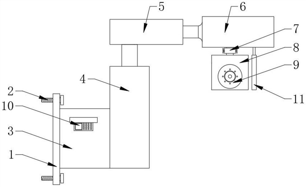
[0023] see figure 1 , the present invention provides a technical solution: an adjustable monitoring device with high flexibility for safety technology prevention engineering, including a mounting plate 1, and fastening bolts 2 are fixedly installed at the four corners of the mounting plate 1, and the mounting plate 1 The right side wall is fixedly equipped with a power supply box 3, the right end of the power supply box 3 is fixedly equipped with a lifter 4 ca...
PUM
 Abstract
Description
Claims
Application Information
PatSnap Eureka turns technology decisions into work you can execute. Powered by our Innovation Knowledge Graph, it runs expert workflows across engineering, life sciences, materials and intellectual property. Get your review-ready output in minutes.


