
Mixing stock bin with suspension type mixing pipe

A blending material and suspension technology, applied in the field of blending silos, can solve problems such as limited support effect of rubber sleeves, falling off and damage of rubber sleeves, and large volume of blending silos, so as to improve vibration effect and reduce friction , The effect of low friction coefficient

Pending Publication Date: 2022-03-25
南京翔瑞智能装备技术股份有限公司 +2
View PDF0 Cites 0 Cited by
  • Summary
  • Abstract
  • Description
  • Claims
  • Application Information

AI Technical Summary

Problems solved by technology

[0003] The existing blending silo is usually provided with a vibrator on the top of the silo to provide vibration power for the blending pipe, and the material in the silo is loosened by the up and down vibration of the blending pipe, so that the material can quickly pass through the feeding hole. However, the volume of the blending silo is relatively large, and the pressure of the material in the silo is very high for the blending tube, so the vibrator needs to operate at a high power to provide sufficient vibration force for the blending tube, which is Elastic supports with strong bearing capacity and strong shock absorbing capacity are required to provide elastic support for the vibrator, and also to control the lateral vibration force of the vibrator, and convert the vibration force of the vibrator into vertical vibration force as much as possible to improve The stability of the up and down vibration of the mixing tube; in addition, the lower end of the mixing tube usually uses a rubber sleeve to limit the lower end of the mixing tube. The supporting effect of the rubber sleeve is limited, and the rubber sleeve often falls off and is damaged.

Method used


Image

  • Mixing stock bin with suspension type mixing pipe
  • Mixing stock bin with suspension type mixing pipe
  • Mixing stock bin with suspension type mixing pipe

Examples


Embodiment 1

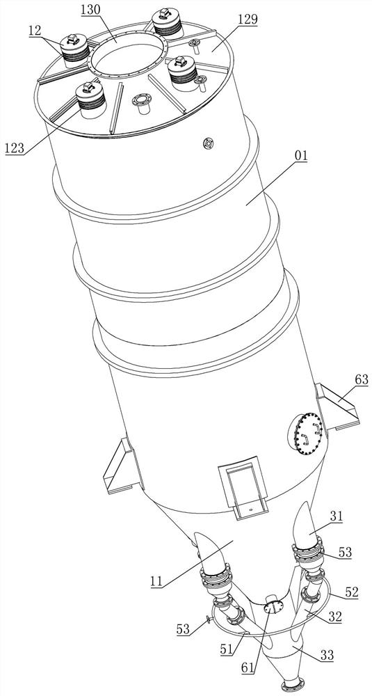
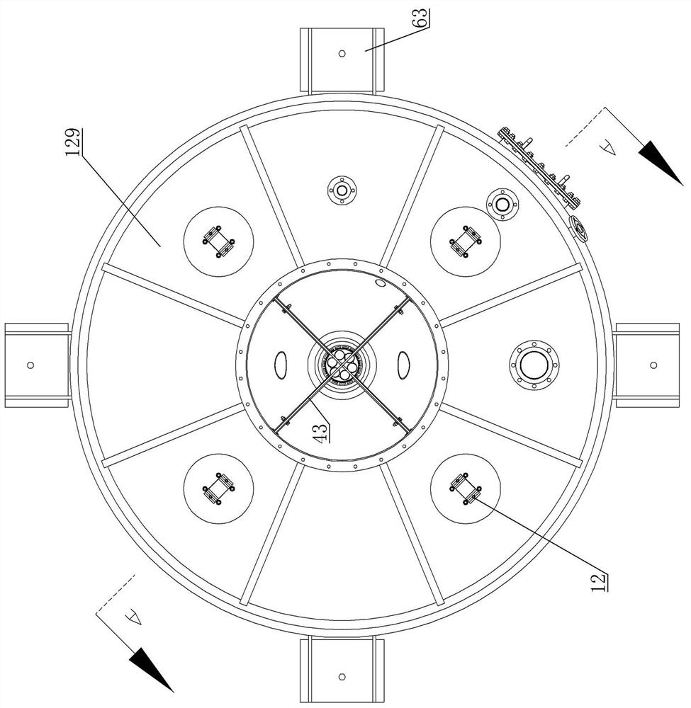
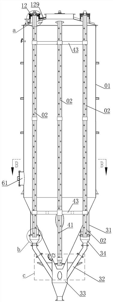
[0033] Embodiment one, refer to the description attached figure 1 - 12. A mixing silo with a suspended mixing pipe, comprising a cylindrical silo with a conical silo bottom at the lower end,

[0034] A plurality of vibrating devices are evenly distributed on the outer edge of the upper end cover plate of the cylindrical silo. The device includes a cylindrical bracket vertically fixed on the surface of the cover plate, a vibrator, and an annular spring. There is a through hole, the annular spring is sleeved on the outside of the cylindrical support, the lower part of the outer surface of the cylindrical support is provided with an annular boss supported on the lower end of the annular spring, the upper end of the annular spring protrudes upwards from the cylindrical support and the upper end of the annular spring is fixedly connected with a vibration The support plate, the vibrator is fixed in the middle of the upper surface of the vibration support plate; the upper end of the...


PUM


Abstract

A cover plate of the mixing bin is provided with a cylindrical support, the cylindrical support is sleeved with an annular spring, the upper end of the annular spring is fixedly connected with a vibrator through a supporting plate, and the upper end of the mixing pipe in the bin is fixedly connected with the supporting plate to form a suspension structure. The vibrator provides up-down vibration power for the mixing pipe, the annular spring serves as an elastic supporting piece, the bearing capacity is high, the buffering and shock absorbing capacity is high, the inner ring and outer ring sleeving structure of the annular spring can well control transverse vibration force, and most vibration force of the vibrator is converted into vertical vibration force; according to the mixing bin, the multi-point supporting ring made of polytetrafluoroethylene plastic is adopted for supporting the lower end of the mixing pipe, the supporting bosses of the multi-point supporting ring can well absorb vibration force of the mixing pipe, the friction coefficient of the multi-point supporting ring is very low, friction force between the supporting bosses and the mixing pipe can be reduced, and the mixing efficiency is improved. And the vibration effect of the mixing pipe is improved.

Description

technical field [0001] The invention relates to the technical field of blending silos, in particular to a blending silo in which a blending pipe is suspended and installed. Background technique [0002] In the industrial field, in order to achieve relatively stable quality requirements for materials, it is necessary to blend different batches of materials. The gravity blending silo uses the full flow form of the materials in the silo to achieve uniform mixing by gravity flow. Materials of different heights in the blending silo enter the blending pipe through the feed holes of different heights on the blending pipe in the silo when the material is unloaded, and then send the materials into the blending chamber below through the conveying pipe, so that the different Batches of materials are simultaneously discharged from the blending chamber to obtain evenly mixed materials. [0003] The existing blending silo is usually provided with a vibrator on the top of the silo to prov...

Claims


Application Information

Patent Timeline
IPC IPC(8): B01F31/60B01F35/43F16F15/06
CPCF16F15/06
Inventor 姜姝易江林方树鹏刘士华邢学涛周甲伟李冰
Owner 南京翔瑞智能装备技术股份有限公司
Learn More