
Automatic bus duct riveting line

A technology of bus duct and riveting wire, applied in the field of bus duct processing equipment, can solve the problems of low processing efficiency and large workload of staff.

Pending Publication Date: 2022-03-25
青岛东山集团有限公司
View PDF9 Cites 1 Cited by
  • Summary
  • Abstract
  • Description
  • Claims
  • Application Information

AI Technical Summary

Problems solved by technology

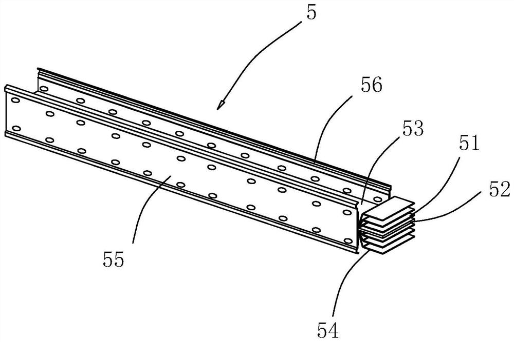
Before riveting, it is necessary to fasten the upper cover plate 53 and the lower cover plate 54 on the upper and lower sides of the copper guide plate 51 respectively, and pre-fix the upper cover plate 53 and the lower cover plate 54 with the copper guide plate 51 by adhesive tape, and then place the left side The plate 55 and the right side plate 56 are fastened on the left and right sides of the copper guide plate 51, and then the assembled bus duct 5 is automatically pushed to the riveting machine, and the riveting machine will cover the upper cover plate 53, the lower cover plate 54, the left side plate 55 and The right side plate 56 is riveted and fixed at one time. The traditional method is to manually push it to the riveting machine. Not only the processing efficiency is low, but also the workload of the staff is heavy.

Method used


Image

  • Automatic bus duct riveting line
  • Automatic bus duct riveting line
  • Automatic bus duct riveting line

Examples


Embodiment Construction

[0041] The following is attached Figure 1-13 The present invention is described in further detail.

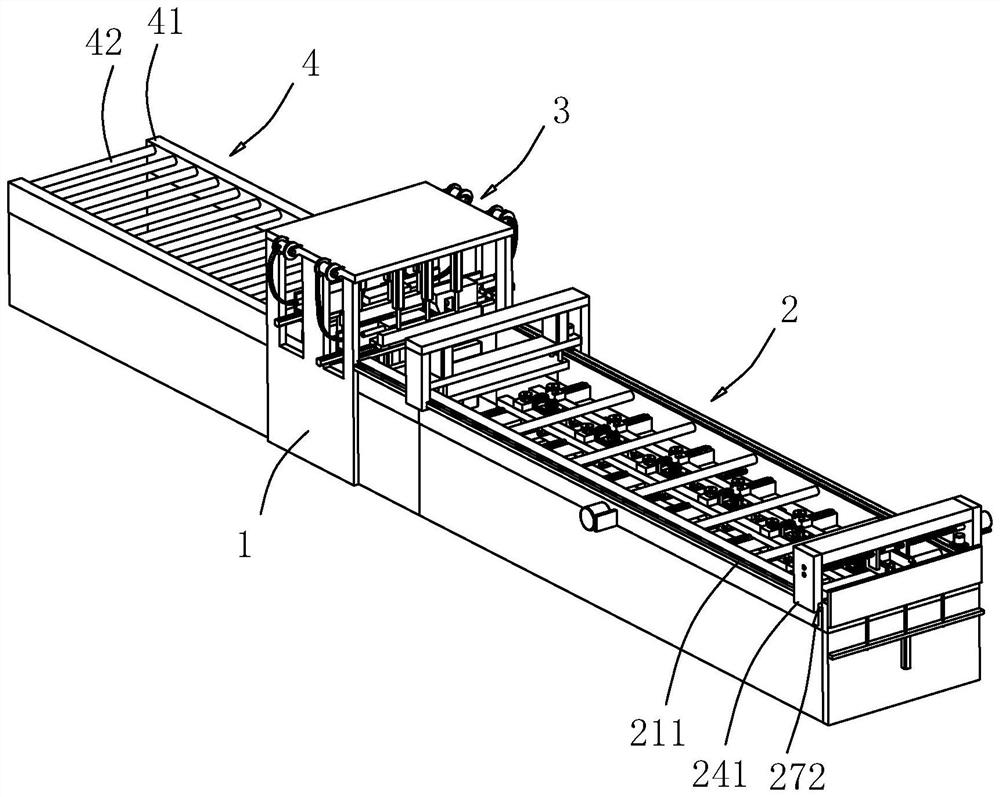
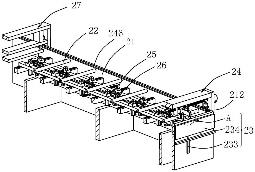
[0042] The embodiment of the invention discloses an automatic busway riveting line. refer to figure 2 , an automatic busway riveting line includes a frame 1, a riveting device 3 is arranged on the frame 1, an automatic feeding device 2 is arranged on one side of the frame 1 located at the riveting device 3, and a discharging device 4 is arranged on the other side The automatic feeding device 2 automatically pushes the spliced ​​busway 5 to the riveting device 3, and the riveting device 3 rives and fixes the two sides of the left side plate 55 with the upper cover plate 53 and the lower cover plate 54 respectively, and simultaneously the right Both sides of the side plate 56 are riveted and fixed with the upper cover plate 53 and the lower cover plate 54 respectively, so as to realize automatic feeding and automatic riveting of the busway 5, improve processing efficiency and...


PUM


Abstract

The invention relates to an automatic bus duct riveting line, and belongs to the field of bus duct processing equipment, the automatic bus duct riveting line comprises a rack, a riveting device is arranged on the rack, and an automatic feeding device is arranged on one side of the rack; the automatic feeding device comprises a feeding frame, a feeding roller is arranged in the feeding frame, the top of the feeding frame is slidably connected with a clamping feeding mechanism, and an intermittent feeding mechanism is arranged at the end, close to the riveting device, of the feeding frame. The clamping and feeding mechanism comprises a door-shaped frame connected to the feeding frame in a sliding mode, a rack is fixedly arranged on one side of the top of the feeding frame in the length direction of the feeding frame, a feeding motor is fixedly arranged on the inner side of the door-shaped frame, and a feeding gear is fixedly arranged on an output shaft of the feeding motor; a first double nipple is rotationally connected to the position, close to the top, in the door-shaped frame, clamping plates are connected to the positions, close to the two ends, of the first double nipple in a threaded mode, a clamping motor is fixedly arranged on the outer side wall of the door-shaped frame, and an output shaft of the clamping motor is fixed to the end of the first double nipple. The device has the effects that the machining efficiency is improved, and the workload of workers is reduced.

Description

technical field [0001] The invention relates to the field of bus duct processing equipment, in particular to an automatic bus duct riveting line. Background technique [0002] The busway is a closed metal device composed of copper and aluminum busbar columns, which is used to distribute large power to various components of the decentralized system. It has increasingly replaced wires and cables in indoor low-voltage power transmission trunk line projects. [0003] A kind of busway 5, refer to figure 1 , comprising an upper cover plate 53, a lower cover plate 54, a left side plate 55 and a right side plate 56, the upper cover plate 53, the lower cover plate 54, the left side plate 55 and the right side plate 56 form a square airtight cavity, the cavity There are four copper guide plates 51 running through the cavity, and the four copper guide plates 51 are parallel to each other and arranged along the length direction of the cavity. An aluminum plate 52 is placed between the...

Claims


Application Information

Patent Timeline
IPC IPC(8): B21J15/32B21J15/10B21J15/38B21J15/44
CPCB21J15/32B21J15/10B21J15/38B21J15/44
Inventor 黄宏斌
Owner 青岛东山集团有限公司
Learn More