Indexable arc thread milling cutter based on aero-engine
An aero-engine, thread milling cutter technology, applied in milling cutters, milling machine equipment, manufacturing tools, etc., can solve the problems of single connection, easy wear of the blade, affecting milling accuracy, etc., to reduce the cost of use, the connection is firm, and the milling quality effect
- Summary
- Abstract
- Description
- Claims
- Application Information
AI Technical Summary
Problems solved by technology
Method used
Image
Examples
Embodiment 1
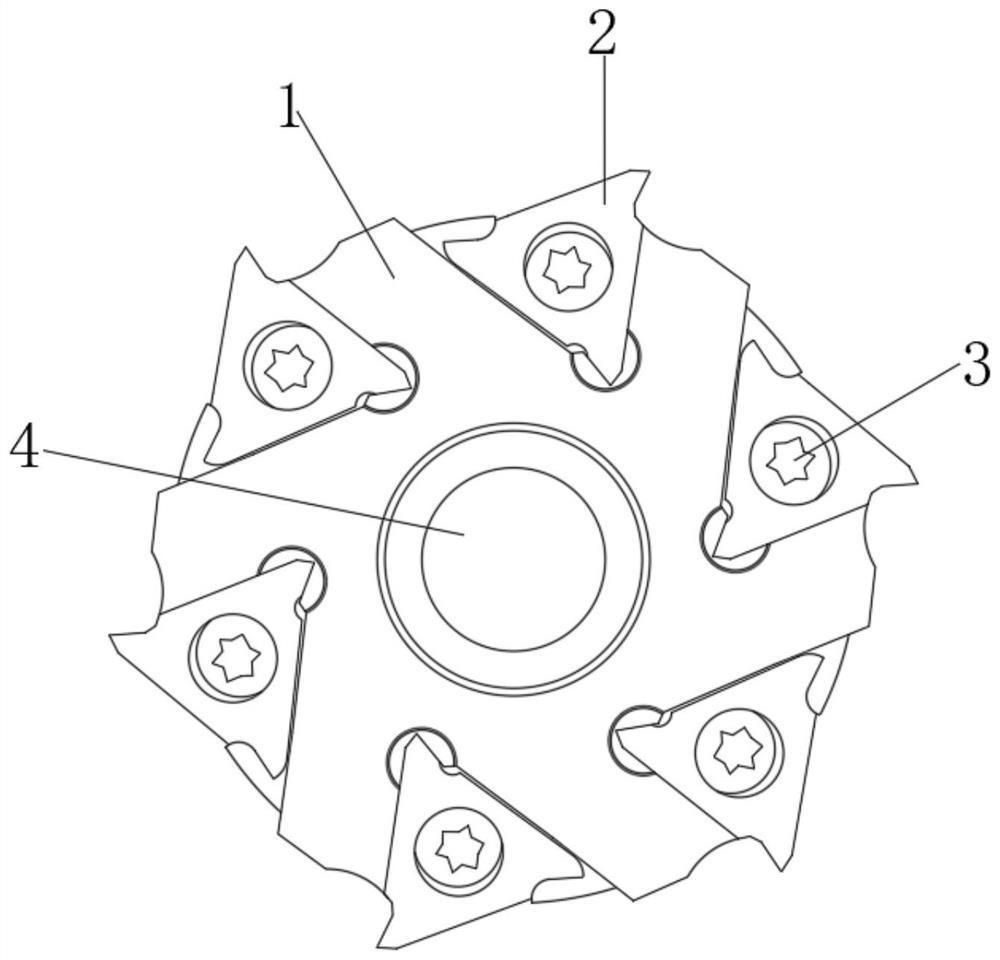
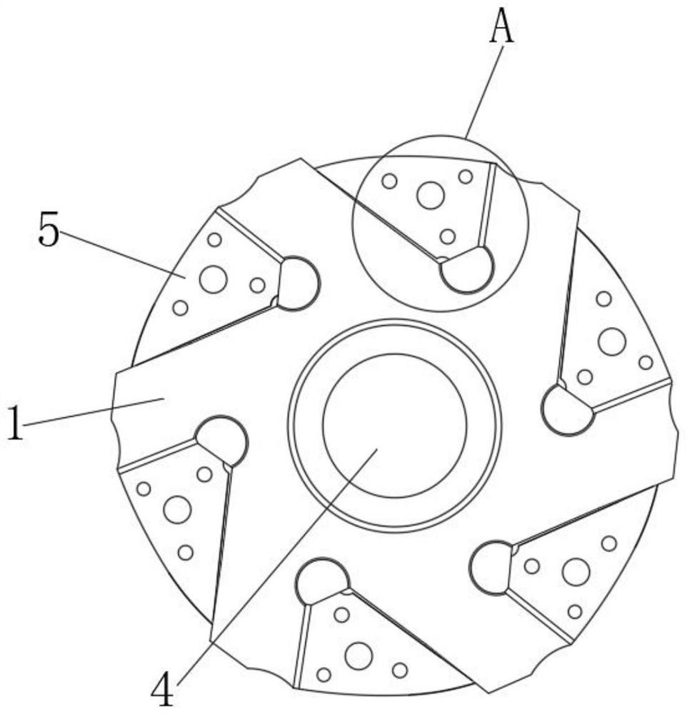
[0026] see Figure 1~5 , an indexable arc thread milling cutter based on aeroengines, including
[0027] The milling cutter body 1 has a plurality of installation parts 5 uniformly arranged on its outer periphery, and the plurality of installation parts 5 are distributed in a circle;
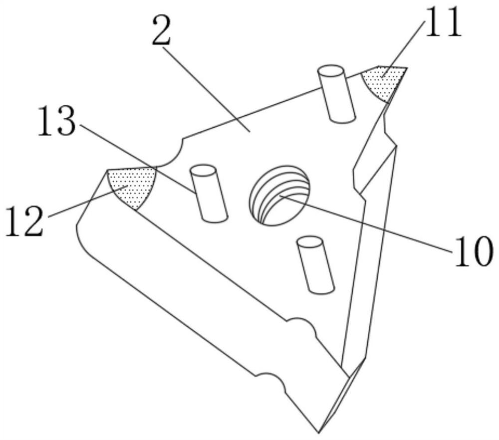
[0028] A plurality of blades 2 are provided and are respectively fixed in each of the installation parts 5 . By arranging a plurality of blades 2 , the milling efficiency can be improved.
[0029] In the embodiment of the present invention, a mounting hole 4 is provided through the center of the milling cutter body 1 to facilitate the connection between the milling cutter body 1 and the tool holder.
[0030] In the embodiment of the present invention, the central position of the blade 2 is provided with a threaded hole 10, and the middle position of the mounting part 5 is provided with a threaded hole 2 8 matched with the threaded hole 10, and the threaded hole 10 A fastening bolt 3 is threade...
Embodiment 2
[0033] see Figure 1~5 , an indexable arc thread milling cutter based on aeroengines, including
[0034] The milling cutter body 1 has a plurality of installation parts 5 uniformly arranged on its outer periphery, and the plurality of installation parts 5 are distributed in a circle;
[0035] A plurality of blades 2 are provided and are respectively fixed in each of the installation parts 5 . By arranging a plurality of blades 2 , the milling efficiency can be improved.
[0036] In the embodiment of the present invention, a sliding groove 14 is provided on one side wall of the limiting hole 7, and a sliding block 15 is slidably connected to the inside of the sliding groove 14, and one side of the sliding block 15 is fixedly connected with The movable block 16 is slidably connected with the limiting hole 7, and a compression spring 6 is connected between the lower side of the movable block 16 and the limiting hole 7, and the elastic force of the compressed spring 6 can make th...
PUM
 Abstract
Description
Claims
Application Information
 - R&D
- Intellectual Property
- Life Sciences
- Materials
- Tech Scout
- Unparalleled Data Quality
- Higher Quality Content
- 60% Fewer Hallucinations
Browse by: Latest US Patents, China's latest patents, Technical Efficacy Thesaurus, Application Domain, Technology Topic, Popular Technical Reports.
© 2025 PatSnap. All rights reserved.Legal|Privacy policy|Modern Slavery Act Transparency Statement|Sitemap|About US| Contact US: help@patsnap.com


