
Self-propelled temporary storage machine for PCBs (printed circuit boards)

A PCB board, self-propelled technology, applied in the field of PCB board self-propelled cache machine, can solve the problems of not having a good reclaiming effect and PCB board congestion, and achieve the effect of reducing friction and improving reclaiming performance.

Pending Publication Date: 2022-03-25
深圳市鹏诚通电子有限公司
View PDF0 Cites 0 Cited by
  • Summary
  • Abstract
  • Description
  • Claims
  • Application Information

AI Technical Summary

Problems solved by technology

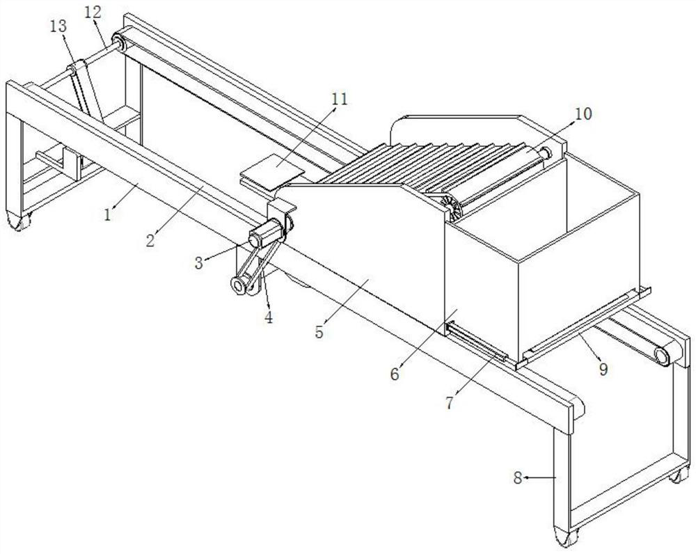
[0003] The PCB board production line includes multiple processes, and the processes are closely connected in sequence. In the actual production process, if there is a problem in a certain process in the middle, the PCB boards delivered by the previous process will be congested. In order to To avoid this problem, it is necessary to use a PCB board buffer machine, but the existing PCB board buffer machine does not have a good material retrieving effect. Therefore, it is urgent to design a PCB board self-propelled buffer machine to solve the above problems

Method used


Image

  • Self-propelled temporary storage machine for PCBs (printed circuit boards)
  • Self-propelled temporary storage machine for PCBs (printed circuit boards)
  • Self-propelled temporary storage machine for PCBs (printed circuit boards)

Examples


Embodiment 1

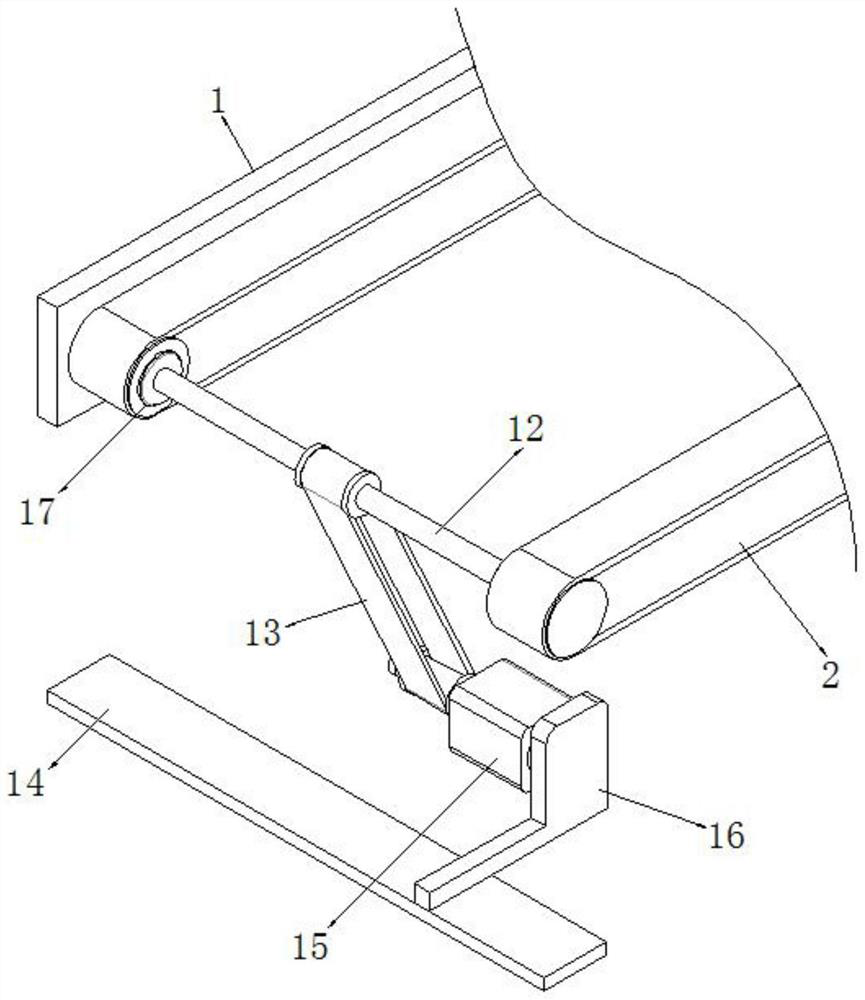
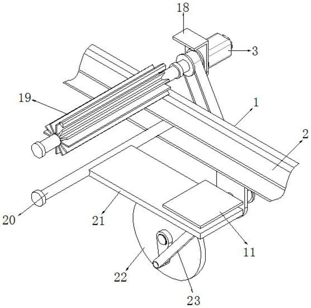
[0032] refer to Figure 1-6 , a self-propelled buffering machine for PCB boards, comprising a support plate 1, the number of support plates 1 is two, and a conveying structure is arranged between opposite sides of the support plate 1, and a first driving mechanism is arranged at one end of the conveying structure , the top sides of the two support plates 1 are connected with side plates 5 by bolts, and one side of the side plates 5 is connected with the same buffer frame 6 by bolts, and the bottom side of one support plate 1 is welded with a fixed plate 24 , and one side of the fixed plate 24 has a through hole, the inner wall of the through hole is connected with the drive shaft 25 through the bearing, a material lifting structure is arranged between the opposite sides of the side plate 5, and one end of the drive shaft 25 is connected to the material lifting structure. One side is provided with a second drive mechanism, the other end of the drive shaft 25 is connected with a...

Embodiment 2

[0042] refer to Figure 7 , a self-propelled buffering machine for PCB boards. Compared with Embodiment 1, one end of the rubber backing plate 11 is bonded with equidistantly distributed and L-shaped rubber rails 34, and the bottom of the rubber rails 34 A V-shaped frame 35 is hinged with one end of the rubber backing plate 11 .

[0043] Working principle: When in use, when the user uses the rubber pad 11 to pull the material, the PCB board can be prevented from falling off through the L-shaped rubber rail 34, and the rubber rail 34 can be prevented from appearing through the support of the V-shaped frame 35 Large deformation problem.


PUM


Abstract

The invention discloses a PCB self-propelled temporary storage machine which comprises two support plates, a conveying structure is arranged between the opposite sides of the support plates, a first driving mechanism is arranged at one end of the conveying structure, and side plates are fixedly connected to one sides of the tops of the two support plates. And one side of each side plate is fixedly connected with the same cache frame, one side of the bottom of one support plate is fixedly connected with a fixing plate, one side of the fixing plate is provided with a through hole, the inner wall of the through hole is connected with a driving shaft through a bearing, and a material lifting structure is arranged between the opposite sides of the side plates. According to the self-propelled temporary storage machine, the stirring plate and the rubber cushion plate are used for stirring the part of PCBs before congestion to the material lifting belt, the PCBs are input into the temporary storage frame through the material lifting belt and the anti-skid protruding strips to be stored, and therefore the whole self-propelled temporary storage machine has the good material taking performance on the PCBs.

Description

technical field [0001] The invention relates to the technical field of PCBs, in particular to a self-propelled buffering machine for PCB boards. Background technique [0002] Printed circuit boards, also known as printed circuit boards, are providers of electrical connections for electronic components. Printed circuit boards are mostly represented by "PCB", and its design is mainly layout design; the main advantage of using circuit boards is that it greatly reduces wiring and assembly errors, and improves the automation level and production labor rate. According to the number of layers of circuit boards, it can be divided into single-sided boards, double-sided boards, four-layer boards, six-layer boards and other multi-layer circuit boards. [0003] The PCB board production line includes multiple processes, and the processes are closely connected in sequence. In the actual production process, if there is a problem in a certain process in the middle, the PCB boards delivered...

Claims


Application Information

Patent Timeline
Patent Type & Authority Applications(China)
IPC IPC(8): B65G15/58B65G23/24B65G65/32
CPCB65G15/58B65G23/24B65G65/32
Inventor 李炳方
Owner 深圳市鹏诚通电子有限公司
Learn More