Optical cable binding wire winding device

A winder and wire-tying technology, which is applied in the field of optical cable wire-tying winders, can solve problems affecting the use of optical cable attachment machines, high cost of wire-tying reels, and low efficiency of manual winding, and achieves simple structure, easy manufacture, and easy winding firming effect

Pending Publication Date: 2022-03-25
CHINA INT TELECOMM CONSTR
View PDF0 Cites 0 Cited by
  • Summary
  • Abstract
  • Description
  • Claims
  • Application Information

AI Technical Summary

Problems solved by technology

[0005] In order to solve the problems that the cost of the wire binding reel required by the optical cable attachment machine is high, the purchase channels are scarce, the manual winding efficiency is low, the winding is not tight, and the use of the optical cable attachment machine is affected, the present invention provides an optical cable binding winder. The purpose is to provide a fiber optic cable binding winder that can perform tight winding, high efficiency, and tight winding. The produced winding wheel can be used normally by the optical cable attachment machine

Method used


Image

  • Optical cable binding wire winding device
  • Optical cable binding wire winding device
  • Optical cable binding wire winding device

Examples


Embodiment Construction

[0034] The present invention will be further described below in conjunction with accompanying drawing and specific embodiment:

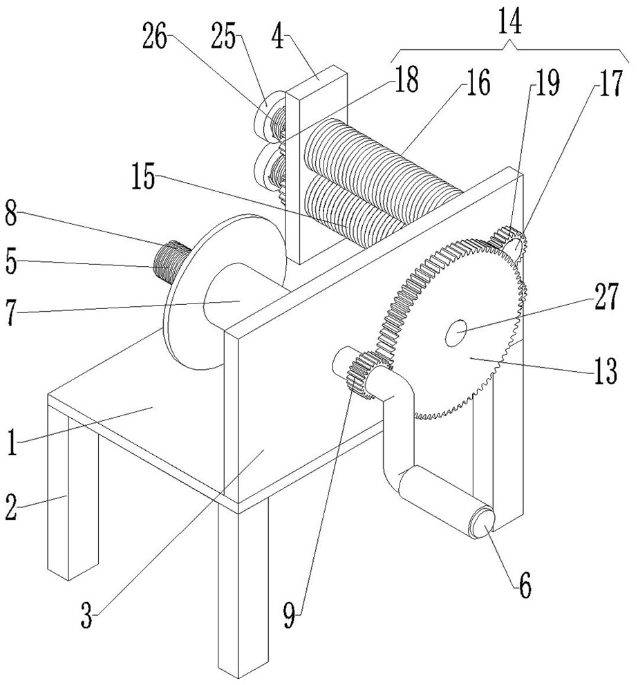
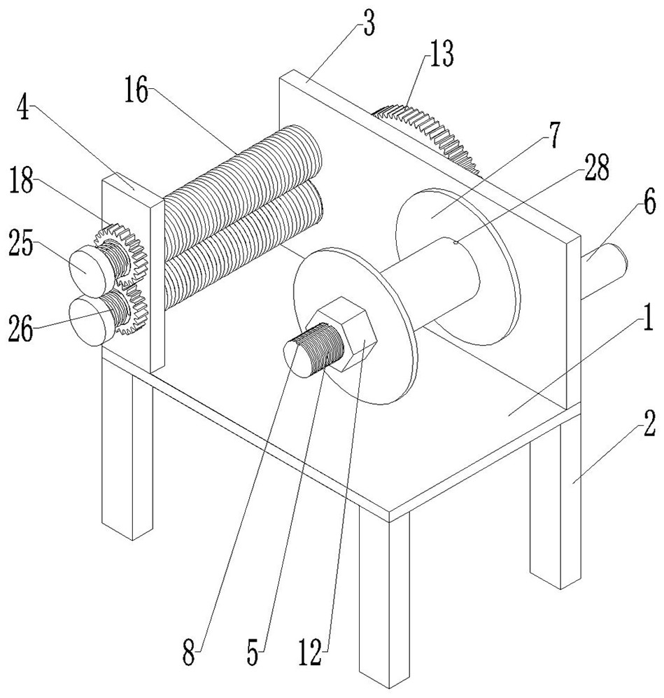
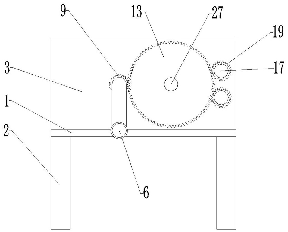
[0035] Such as Figure 1 to Figure 8 As shown, an optical cable binding winder includes a base, a winding portion and a guiding portion;

[0036] The base includes a base plate 1 and supporting legs 2, the base plate 1 is a square plate body, the four corners of the lower surface of the base plate 1 are provided with supporting legs 2, and the front end of the upper surface of the base plate 1 is provided with a bearing plate 3, and the bearing plate 3 is Vertical square plate body, carrying plate 3 is provided with the mounting hole that runs through the front and rear sides of carrying plate 3, and described mounting hole is the circular through hole, and the right end of carrying plate 3 is provided with the first circular through hole and the second circular through hole. Circular through holes, the first circular through hole and the second cir...


PUM


Abstract

The invention relates to an optical cable binding wire winder which comprises a base, a winding part and a guiding part, the base comprises a base plate and supporting legs, the winding part comprises a winding shaft, a handle and a winding wheel, the guiding part comprises a first guiding roller and a second guiding roller, and the first guiding roller and the second guiding roller are consistent in structure and size and are vertically opposite. The first guide roller comprises a roller sleeve, a mandrel, a second gear and a third gear, and a transmission gear is arranged on the front side face of the bearing plate. The iron wire can be tightly wound on the reel, the speed is high, the efficiency is high, winding is compact, and the manufactured reel can be normally used by an optical cable attaching machine.

Description

technical field [0001] The invention relates to the technical field of wire binding and winding equipment, in particular to an optical cable binding and winding device. Background technique [0002] Tie wire is made of high-quality low-carbon steel wire rod. Through high-quality low-carbon steel through drawing forming, pickling and derusting, high-temperature annealing, hot-dip galvanizing, cooling and other processes, it has good toughness and elasticity and is widely used. It is widely used in construction, handicrafts, woven wire mesh, highway guardrail, product packaging and daily civilian use. [0003] In the daily maintenance of optical cables, there are often scattered lines in overhead lines, and maintenance personnel need to use optical cable attachment machines to bundle and arrange them. The cost of wire binding reels required by optical cable attachment machines is relatively high, and purchase channels are scarce. Usually, the iron wire of the same specificati...

Claims


Application Information

Patent Timeline
IPC IPC(8): B65H54/28B65H54/44B65H59/10
CPCB65H54/2842B65H54/44B65H59/10B65H2701/39
Inventor 杨尚明宋彦韬刘自力袁少凡李阳王中正刘昊
Owner CHINA INT TELECOMM CONSTR
Why Eureka
Try Eureka