
Construction method of inclined column conversion frame shear wall structure

A construction method, shear wall technology, applied to walls, building components, building structures, etc., can solve problems such as high manpower and material costs, low reliability, and complicated construction processes

Pending Publication Date: 2022-03-25
广州市设计院集团有限公司
View PDF7 Cites 2 Cited by
  • Summary
  • Abstract
  • Description
  • Claims
  • Application Information

AI Technical Summary

Problems solved by technology

Since the transfer is located on the bottom floor of the tower, when the slope of the inclined column is large, the floor beam will generate a large horizontal tension under the action of gravity load, which will have an adverse effect on the floor structure and low reliability
Moreover, in the traditional construction of inclined columns to convert shear walls, large-scale equipment is usually required for the installation and construction of inclined columns. The construction process is complicated, and the cost of manpower and material resources is high.

Method used


Image

  • Construction method of inclined column conversion frame shear wall structure
  • Construction method of inclined column conversion frame shear wall structure
  • Construction method of inclined column conversion frame shear wall structure

Examples


Embodiment Construction

[0037] In order to make the above objects, features, and advantages of the present invention, the specific embodiments of the present invention will be described in detail below with reference to the accompanying drawings. Many specific details are set forth in the following description to fully understand the invention. However, the present invention can be implemented in many different fails thereof, and those skilled in the art can do similar improvements without departing from the connotation of the present invention, and thus the present invention is not limited by the specific embodiments disclosed below.

[0038] In the description of the present invention, it is to be understood that the terms "center", "longitudinal", "horizontal", "length", "width", "thickness", "upper", "under", "front", " After "," left "," right "," vertical "," horizontal "," top "," bottom "," internal "," outside "," clockwise "," counterclock "," axial " , "Radial", "circumferential" or the like, ...


PUM


Abstract

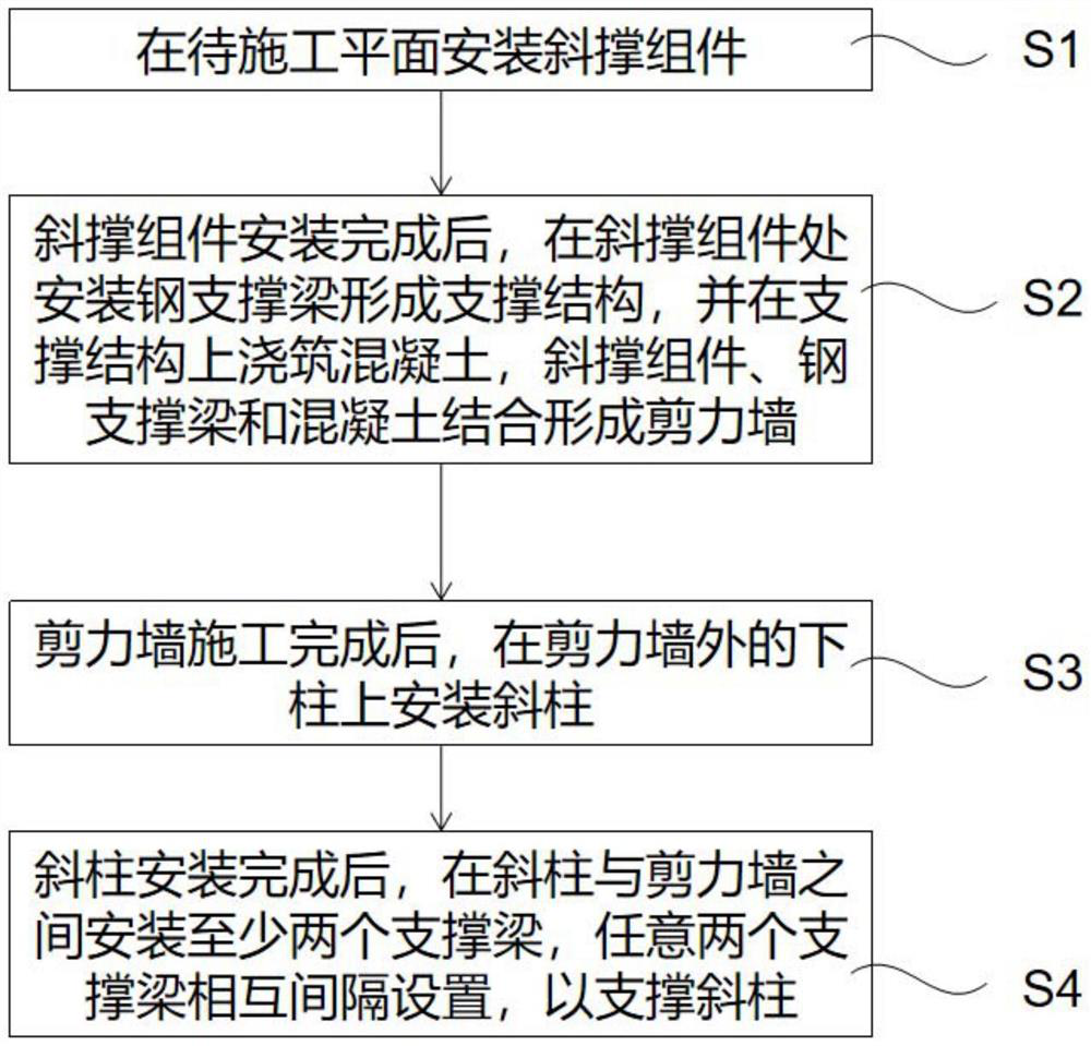
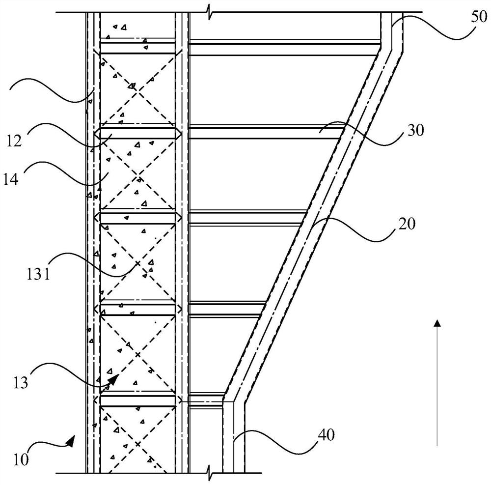
The invention discloses a construction method of an inclined column conversion frame shear wall structure. The construction method comprises the following steps that inclined strut assemblies are installed on a to-be-constructed plane; after the inclined strut assemblies are installed, steel supporting beams are installed at the inclined strut assemblies to form a supporting structure, concrete is poured on the supporting structure, and the inclined strut assemblies, the steel supporting beams and the concrete are combined to form a shear wall; after construction of the shear wall is completed, inclined columns are installed on the lower columns outside the shear wall; after the batter post is installed, at least two supporting beams are installed between the batter post and the shear wall, and any two supporting beams are arranged in a spaced mode so as to support the batter post. And the diagonal bracing assembly improves the shear bearing capacity of the shear wall. The bearing force transmitted by the upper column is transferred into the force in the horizontal direction through the inclined column, the force is transmitted into the shear wall through the supporting beam, the force is transmitted and dispersed in cooperation with the inclined strut assembly, the overall structure is simple and reasonable, the shear bearing capacity is high, the connection reliability is ensured, and the problem that concrete cracks are caused by large horizontal force generated by inclination of the inclined column is solved.

Description

Technical field [0001] The present invention relates to the field of building construction, and in particular, the construction method of a slope column conversion frame shear wall structure. Background technique [0002] In the frame-shear wall (or core) structure system, it is often encountered in the actual engineering that the frame column can not fall in the bottom floor. The transmission is directly directly when the slant column is converted, and the overall structural stiffness is small, and it is conducive to the seismic. Since the conversion is located in the bottom floor of the tower, when the slope of the slant column is large, the floor beam will produce a large horizontal tension under the gravity load, the tension is adversely affected on the floor structure, and the reliability is low. In the construction of the traditional slope conversion shear wall, the installation construction of the laminated column is usually required, and the construction process is compli...

Claims


Application Information

Patent Timeline
IPC IPC(8): E04B2/56E04G21/14
CPCE04B2/56E04G21/14
Inventor 赵松林朱祖敬缪嘉荣吕鹏王燕珺
Owner 广州市设计院集团有限公司
Learn More