Indoor pipeline sound insulation and noise reduction structure convenient to expand and construct

A technology for inner pipes and pipes, applied in the field of sound insulation and noise reduction structure of indoor pipes, can solve the problems of easy deformation and aging, large floor space, complicated construction, etc., and achieve the effect of reducing floor space, facilitating expansion and construction, and facilitating construction.

Active Publication Date: 2022-03-25
深圳市众华装饰工程有限公司
View PDF7 Cites 0 Cited by
  • Summary
  • Abstract
  • Description
  • Claims
  • Application Information

AI Technical Summary

Problems solved by technology

[0003] At present, commercial residential buildings are mostly equipped with standpipes indoors, which will generate a lot of noise when draining water through the standpipes, which has caused troubles to people's lives. Generally, it is necessary to perform sound insulation and noise reduction treatment on indoor standpipes during interior decoration. At present A better solution is to use bricks to build pillars to surround the pipeline, then add cement mortar and stick steel wire mesh, and finally tiles, which are not easy to deform and have better sound insulation effects, but the construction is complicated and occupies a large area, or the pipeline should be installed first. Set the keel frame on the outside and then wrap the sound insulation cotton to make the exterior decoration surface, but it is easy to deform and age. The above-mentioned indoor pipe sound insulation and noise reduction construction method is difficult to pre-adjust and expand according to the pipe size and the actual distance from the wall

Method used


Image

  • Indoor pipeline sound insulation and noise reduction structure convenient to expand and construct
  • Indoor pipeline sound insulation and noise reduction structure convenient to expand and construct
  • Indoor pipeline sound insulation and noise reduction structure convenient to expand and construct

Examples


Embodiment

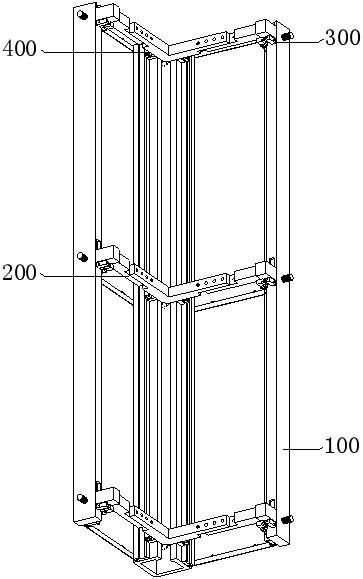
[0051] Such as Figure 1-Figure 15 As shown, the indoor pipeline sound insulation and noise reduction structure that is convenient for expansion and construction according to the embodiment of the present application includes a supporting and hanging mechanism 100, an adjusting frame mechanism 200, a frame limiting and locking mechanism 300, and a keel positioning and fixing mechanism 400. The frame mechanism 200 is set on the support and dry hanging mechanism 100, and can be flexibly adjusted and set according to the pipe size and the distance from the wall. On the frame mechanism 200, it is convenient to limit and lock the adjustment frame mechanism 200.

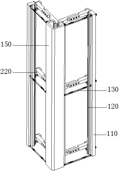
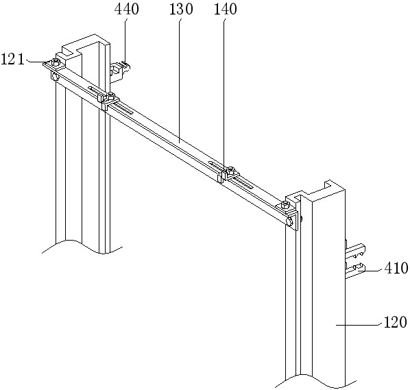
[0052] According to some embodiments of the present application, such as Figure 1-Figure 3 and Figure 5-Figure 8 As shown, the supporting and hanging mechanism 100 includes a vertical rod 110, a keel 120, an angle steel 130, a dry hanging piece 140 and a corner frame 150. The two vertical rods 110 are arranged side by ...


PUM


Abstract

The invention provides an indoor pipeline sound insulation and noise reduction structure convenient to expand and construct, and belongs to the field of indoor construction.The indoor pipeline sound insulation and noise reduction structure comprises a supporting and dry hanging mechanism and an adjusting frame mechanism, and the supporting and dry hanging mechanism comprises vertical rods, keels, angle steel, dry hanging pieces and corner frames; the keel is arranged on the sides, away from the vertical face of a wall corner, of the vertical rods, the multiple pieces of angle steel are transversely arranged on the sides, away from a pipeline, of the keel, the adjusting frame mechanism comprises first connecting blocks, transverse frames and a corner bracket, the first connecting blocks on the two vertical rods are correspondingly arranged, and the transverse frames are arranged at the two ends of the corner bracket correspondingly. And the keels are arranged on the two sides of the corner frame correspondingly, the two ends of the angle steel are fixedly connected to the sides, away from the pipeline, of the two keels correspondingly, the span of the supporting structure can be flexibly adjusted, construction is convenient, and the occupied area is reduced.

Description

technical field [0001] The application relates to the field of indoor construction, in particular, to an indoor pipeline sound insulation and noise reduction structure that is convenient for expansion and construction. Background technique [0002] The indoor drainage system is to collect the water used by indoor people in daily life and industrial production, and discharge it into the outdoor sewage pipe in time directly or after partial treatment. In order to get rid of rain and snow on the roof, indoor rainwater channels are sometimes set up to discharge rainwater into outdoor rainwater channels or combined sewers. Standpipes are an important part of the indoor drainage system of modern buildings, through which rainwater can be discharged in time Houses accumulate water in the weather. In addition, the riser is connected to various indoor water facilities to facilitate the timely discharge of waste water. [0003] At present, commercial residential buildings are mostly e...

Claims


Application Information

Patent Timeline
Patent Type & Authority Applications(China)
IPC IPC(8): E04F13/073E04F13/23E04B1/86
CPCE04F13/0733E04F13/0803E04B1/86
Inventor 安昌顺
Owner 深圳市众华装饰工程有限公司
Why Eureka
Try Eureka