Flatness detection equipment for constructional engineering and use method of flatness detection equipment

A technology for flatness detection and construction engineering, applied in measuring devices, instruments, etc., can solve the problems of time-consuming, labor-intensive, inconvenient recording, low efficiency, etc., and achieve the effect of improving detection efficiency and reducing work burden

Inactive Publication Date: 2022-03-25
谢俊娥
View PDF0 Cites 2 Cited by
  • Summary
  • Abstract
  • Description
  • Claims
  • Application Information

AI Technical Summary

Problems solved by technology

[0002] Flatness detection is sometimes also called frontage detection and co-planarity detection. In the prior art, a level is commonly used as a flatness detection device during construction of a construction project. The level is based on the principle of the level of the liquid surface. Face against the wall or the ground, use the feeler gauge to measure the gap between the level and the wall or the ground. In the actual measurement, the feeler gauge needs to measure at multiple positions along the length of the level, and then The test data is obtained by reading the value of the feeler gauge. In this method, the staff need to measure repeatedly during the measurement, which is time-consuming and laborious, which increases the work burden of the test personnel, and is inconvenient to record, and the efficiency is low.

Method used


Image

  • Flatness detection equipment for constructional engineering and use method of flatness detection equipment
  • Flatness detection equipment for constructional engineering and use method of flatness detection equipment
  • Flatness detection equipment for constructional engineering and use method of flatness detection equipment

Examples


Embodiment Construction

[0044] In order to further understand the features, technical means, and the specific purposes, functions achieved, which will be described in further detail below with reference to the accompanying drawings.

[0045] Such as Figure 1-12 Looking:

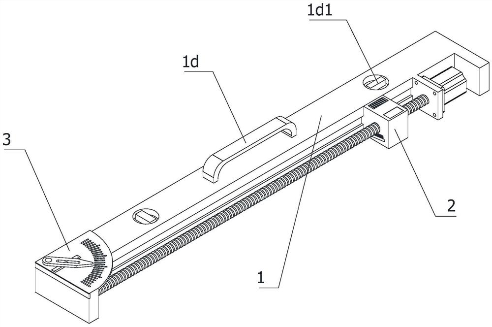
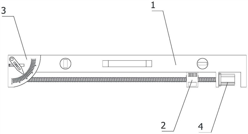
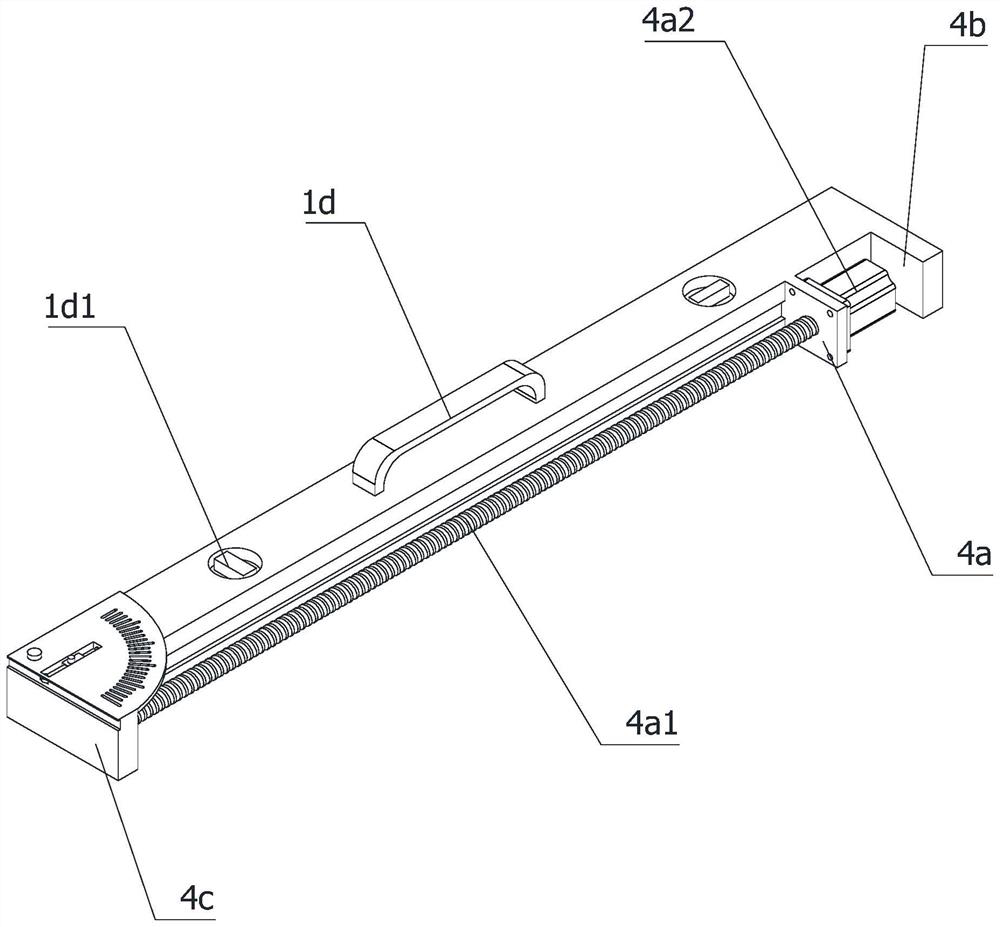
[0046] A planar detecting device for construction engineering, including measuring ruler 1 and a first measuring head 2 for measuring the planarity of the building wall or ground, and a first detection surface 1a is also provided on the measurement ruler 1. The second detection surface 1b, the first slide rail 1c, the first slide 3a and the second measuring head 3 for measuring the angle of the building wall or the ground, and the first detecting surface 1a is located at the bottom of the measuring ruler 1. The second detecting surface 1b is located one of the ends of the width direction of the measuring ruler 1, and the first slide rail 1c is disposed in the longitudinal direction of the measuring ruler 1, and the measuring ruler 1 is ...


PUM


Abstract

The invention relates to the technical field of flatness detection of constructional engineering, in particular to flatness detection equipment for constructional engineering and a use method thereof, and the flatness detection equipment comprises a measuring scale, and a first measuring head, a first detection surface, a second detection surface, a first sliding rail, a first sliding chute and a second measuring head which are arranged on the measuring scale, the first detection surface is located at the bottom of the measuring ruler, the second detection surface is located at one end of the measuring ruler in the width direction, the first sliding rail is arranged on the side wall of the measuring ruler, the first measuring head is slidably connected to the first sliding rail, the first sliding groove is located at one end of the top of the measuring ruler, and the second measuring head is slidably connected to the first sliding groove. The flatness of the wall surface or the ground is detected by sliding the first measuring head, a plurality of measuring points of the measuring scale do not need to be repeatedly measured through a feeler gauge, the detection efficiency is improved, the workload of workers is relieved, the second measuring head is convenient to read an angle more accurately, whether the angle is vertical or not is judged, and the detection precision is improved.

Description

Technical field [0001] The present invention relates to the field of planar detection technology of building engineering, and in particular, to a flatness detection device for construction engineering and how to use it. Background technique [0002] Placed detection is sometimes called positive surface detection, common-faced detection, prior art construction project is commonly used in planar detection devices, horizontal rule is the principle of using liquid level, by detecting horizontal ruler On the wall or ground, the plug is measured for the gap between the horizontal foot or the ground or the ground, in the actual measurement, the plug is required to perform multiple locations in the longitudinal direction of the horizontal foot. By reading the values ​​of the plug, the staff needs repeated measurement, and the labor time, and the operational force force, and it is not convenient to record, the efficiency is low. Inventive content [0003] Based on this, it is necessary f...

Claims


Application Information

Patent Timeline
Patent Type & Authority Applications(China)
IPC IPC(8): G01B21/30
CPCG01B21/30
Inventor 谢俊娥
Owner 谢俊娥
Why Eureka
Try Eureka