Optical fiber refractive index temperature coefficient testing method based on optical fiber gyroscope system

A technology of optical fiber refractive index and fiber optic gyroscope, which is applied in the direction of optical instrument testing, testing of optical fiber/optical waveguide equipment, testing of machine/structural components, etc. The temperature coefficient of the refractive index is not comparable, and the internal strain difference of the optical fiber is different, so as to achieve convenient and accurate measurement, reduce the influence of the test environment, and avoid the effect of temperature unevenness

Pending Publication Date: 2022-03-25
BEIJING AEROSPACE TIMES OPTICAL ELECTRONICS TECH
View PDF0 Cites 2 Cited by
  • Summary
  • Abstract
  • Description
  • Claims
  • Application Information

AI Technical Summary

Problems solved by technology

However, this test method ignores the influence of the internal strain of the optical fiber on the test results under temperature changes, which reduces the accuracy of the temperature coefficient of refraction index of the polarization-maintaining fiber.
In addition, due to the large differences in doping elements and doping concentrations in different manufacturers and different batches of optical fibers, the linear expansion coefficient of optical fibers under temperature changes is different, resulting in large differences in the internal strain of optical fibers under temperature changes.
Under the premise of ignoring the large difference in the internal strain of the fiber, the temperature coefficient of the polarization-maintaining fiber obtained by the test is not comparable. Referring to the temperature coefficient of the polarization-maintaining fiber measured by this method, there will be errors in screening the polarization-maintaining fiber for fiber optic gyroscope.

Method used


Image

  • Optical fiber refractive index temperature coefficient testing method based on optical fiber gyroscope system
  • Optical fiber refractive index temperature coefficient testing method based on optical fiber gyroscope system
  • Optical fiber refractive index temperature coefficient testing method based on optical fiber gyroscope system

Examples


Embodiment Construction

[0040] The following describes the present invention in detail, and the features and advantages of the present invention will become more clear and definite along with these descriptions.

[0041] The word "exemplary" is used exclusively herein to mean "serving as an example, embodiment, or illustration." Any embodiment described herein as "exemplary" is not necessarily to be construed as superior or better than other embodiments. While various aspects of the embodiments are shown in drawings, the drawings are not necessarily drawn to scale unless specifically indicated.

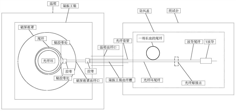
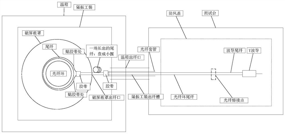
[0042]A method for testing the temperature coefficient of refraction index of a polarization-maintaining optical fiber for an optical fiber gyroscope of the present invention comprises the following steps:

[0043] a. Process the fiber optic ring pigtails so that one end of the pigtail is longer than the other end, which are recorded as long and short pigtails respectively, and the difference between the le...


PUM

PropertyMeasurementUnit
diameteraaaaaaaaaa

Abstract

The invention discloses an optical fiber refractive index temperature coefficient testing method based on an optical fiber gyroscope system, which comprises the following steps of: firstly, enabling tail fibers at two ends of an optical fiber ring to be respectively a long tail fiber and a short tail fiber, connecting the two tail fibers into an optical fiber gyroscope, and then testing the refractive index temperature coefficient of the optical fiber under the same temperature change condition; and respectively testing zero offset error curves of the fiber-optic gyroscope in two states of the long tail fiber longer than the short tail fiber outside the incubator and inside the incubator, and finally, selecting a zero offset error value of any one of the two test curves at the same temperature, and calculating to obtain the refractive index temperature coefficient of the optical fiber. The method can be applied to the testing and screening process of the polarization-maintaining optical fiber for the fiber-optic gyroscope, the refractive index temperature coefficient of the polarization-maintaining optical fiber used by a core optical device optical fiber ring of the fiber-optic gyroscope is accurately tested, the influence of strain generated by the optical fiber under the temperature change is considered on the premise of reducing the influence of the testing environment as much as possible, and the testing accuracy is improved. The influence of optical fiber strain on a test result is eliminated, and the test accuracy of the refractive index temperature coefficient of the polarization maintaining optical fiber is improved.

Description

technical field [0001] The invention belongs to the technical field of optical fibers and optical fiber gyroscopes, and relates to a method for testing the temperature coefficient of refraction index of polarization-maintaining optical fibers used in optical fiber gyroscopes. Background technique [0002] Fiber optic gyroscope is a fiber optic angular rate sensor based on the Sagnac effect, which has the advantages of small size, high precision, long life, and large dynamic range. Fiber optic gyroscopes are not only used for high-precision position control of aircraft and ship navigation and missile guidance, but also for vehicle guidance, robotics and automation control systems in the civilian market. [0003] As a sensitive core component of the fiber optic gyroscope, the performance of the fiber optic ring directly affects the accuracy of the fiber optic gyroscope. The zero-bias error of the fiber optic gyro is significantly affected by the ambient temperature, and the t...

Claims


Application Information

Patent Timeline
Patent Type & Authority Applications(China)
IPC IPC(8): G01M11/00G01C25/00
CPCG01M11/30G01C25/005
Inventor 范运强孙彦凤谭翠齐琦
Owner BEIJING AEROSPACE TIMES OPTICAL ELECTRONICS TECH
Why Eureka
Try Eureka