Device for detecting falling of gluing positions of inner and outer lenses of automobile

A lens and gluing technology, applied in the direction of testing optical properties, etc., can solve problems such as affecting the work efficiency of workers, consuming physical strength, and low safety, and achieving the effect of saving physical strength, improving work efficiency, and high safety.

Inactive Publication Date: 2022-03-25
YINGTAN KSD ELECTRONICS PLASTIC
View PDF0 Cites 0 Cited by
  • Summary
  • Abstract
  • Description
  • Claims
  • Application Information

AI Technical Summary

Problems solved by technology

[0003] When the current factory inspects the reflector, most of the workers hold the reflector in one hand and the hitting block in the other, and use the hitting block to knock the reflector several times to test the reflector. Because this method requires workers to continuously hold the hitting block to knock on a batch of reflectors, it consumes more energy and easily affects the subsequent work efficiency of the workers, and when the lens falls off, it is easy to cause damage to the hands of the workers. cuts, less safe

Method used


Image

  • Device for detecting falling of gluing positions of inner and outer lenses of automobile
  • Device for detecting falling of gluing positions of inner and outer lenses of automobile
  • Device for detecting falling of gluing positions of inner and outer lenses of automobile

Examples


Embodiment 1

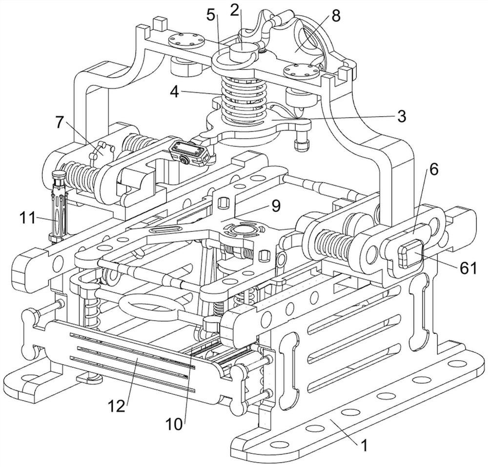
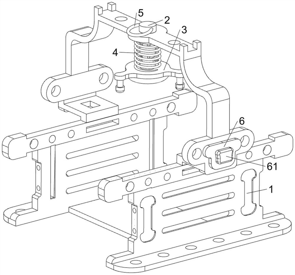
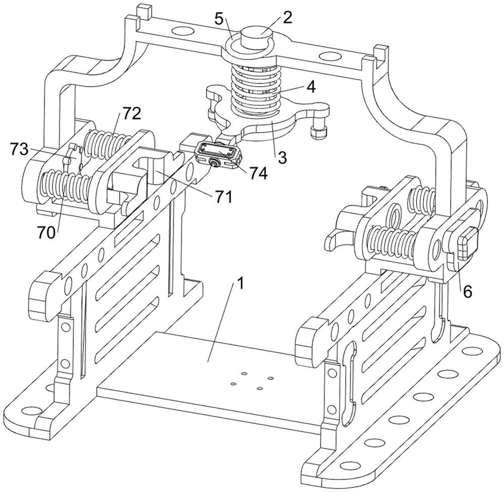
[0038] A device for detecting the falling off of the glued part of the inner and outer lenses of the automobile, including a support frame 1, a lifting rod 2, a hitting block 3, a compression spring 4, a pull ring 5, a control panel 6, a start switch 61, a clamping mechanism 7, Turning mechanism 8, unloading mechanism 9 and transmission mechanism 10, refer to Figure 1-Figure 10As shown, the lifting rod 2 is slidingly provided in the middle of the upper part of the support frame 1, and the bottom of the lifting rod 2 is welded with a hitting block 3. When the hitting block 3 moves to contact with the reflective mirror, it can knock on the reflective mirror. A compression spring 4 is provided between the top of the block 3 and the support frame 1, a pull ring 5 is provided on the upper side of the lifting rod 2 in a rotating manner, a control panel 6 is provided in the middle of the right side of the support frame 1, and a starter is provided on the right side of the control pan...

Embodiment 2

[0045] On the basis of Embodiment 1, a conversion mechanism 11 is also included, and the conversion mechanism 11 includes a second limit rod 110, a tension spring 111, a second rotating shaft 112, a reel 113, a pull cord 114, a second Connecting block 115, second electric push rod 116, control switch 117 and second pressure sensor 118, refer to figure 1 , Figure 11 and Figure 12 As shown, the front and rear sides of the lower part of the inner side of the support frame 1 are symmetrically provided with a second limiting rod 110, and the upper side of the second limiting rod 110 is slidably connected with the sliding frame 96 on the same side, and the left and right sides of the sliding frame 96 bottom Tension springs 111 are arranged between the side and the second limit rod 110 on the same side, and the front and rear sides of the inner lower part of the support frame 1 are symmetrically rotated left and right to be provided with a second rotating shaft 112, and the second...


PUM


Abstract

The invention relates to a device for detecting falling of a lens gluing position, in particular to a device for detecting falling of automobile inner and outer lens gluing positions. The invention aims to provide the device for detecting the falling of the gluing positions of the inner and outer lenses of the automobile, which can automatically knock a reflective mirror and is relatively high in safety. The device comprises a supporting frame, a lifting rod, a striking block, a compression spring, a pull ring and the like, the lifting rod is slidably arranged in the middle of the upper portion of the supporting frame, the striking block used for striking a reflective mirror is arranged at the bottom of the lifting rod, the compression spring is arranged between the top of the striking block and the supporting frame, and the pull ring is arranged on the top of the striking block. And a pull ring is rotationally arranged on the upper side of the lifting rod. According to the device, the driving motor starts to work by pressing the starting switch once, so that the concave-convex block rotates, the striking block automatically and intermittently strikes the reflective mirror, the physical strength of people is saved, and the working efficiency is improved.

Description

technical field [0001] The invention relates to a device for detecting the peeling off of the glued part of the lens, in particular to a device for detecting the peeled off of the glued part of the inner and outer lenses of the automobile. Background technique [0002] At present, after the production of the reflector of the car, the lens is usually fixed by coating, so that the lens is easy to fall off from the reflector. Therefore, in order to prevent the lens from falling off in the reflector, most factories will carry out a Sampling inspection, so as to guarantee the safety of the product. [0003] When the current factory inspects the reflector, most of the workers hold the reflector in one hand and the hitting block in the other, and use the hitting block to knock the reflector several times to test the reflector. Because this method requires workers to continuously hold the hitting block to knock on a batch of reflectors, it consumes more energy and easily affects th...

Claims


Application Information

Patent Timeline
Patent Type & Authority Applications(China)
IPC IPC(8): G01M11/02
CPCG01M11/02
Inventor 程鲜红潘斌
Owner YINGTAN KSD ELECTRONICS PLASTIC
Why Eureka
Try Eureka