
Calibration method, calibration system and calibration target for linear structured light imaging and measurement system using calibration target

A line-structured light and calibration method technology, applied in the field of visual measurement, can solve problems such as large world coordinate errors, reduced recognition accuracy, and unfavorable calibration calculations

Pending Publication Date: 2022-03-25
上海柏楚电子科技股份有限公司
View PDF0 Cites 3 Cited by
  • Summary
  • Abstract
  • Description
  • Claims
  • Application Information

AI Technical Summary

Problems solved by technology

[0005] However, the existing line-structured cursor calibration method cannot accurately obtain the world coordinates corresponding to the pixels, especially in welding application scenarios, the more motion joints and degrees of freedom the greater the world coordinate error obtained
The calibration teeth on the existing calibration target are set continuously, so many unnecessary corners will appear when processing the structured light profile image, which undoubtedly increases the difficulty of recognition, and also reduces the recognition accuracy, which is not conducive to calibration calculate
In addition, in the calibration process of the existing method, each time the sensor is moved to a different position to measure the pixel coordinates of the target point and the corresponding world coordinates, multiple parameters need to be measured and recorded for calibration, and the operation process is relatively cumbersome.

Method used


Image

  • Calibration method, calibration system and calibration target for linear structured light imaging and measurement system using calibration target
  • Calibration method, calibration system and calibration target for linear structured light imaging and measurement system using calibration target
  • Calibration method, calibration system and calibration target for linear structured light imaging and measurement system using calibration target

Examples


Embodiment Construction

[0039] The present invention will be further described below in conjunction with specific embodiment and accompanying drawing, set forth more details in the following description in order to fully understand the present invention, but the present invention can obviously be implemented in many other ways different from this description Those skilled in the art can make similar promotions and deductions based on actual application situations without violating the spirit of the present invention. Therefore, the content of this specific embodiment should not limit the protection scope of the present invention.

[0040] Unless otherwise defined, the technical terms or scientific terms used in the claims and the description shall have the ordinary meanings understood by those skilled in the technical field to which the present invention belongs. "First", "second" and similar words used in the description and claims of the present application do not indicate any sequence, quantity or ...


PUM


Abstract

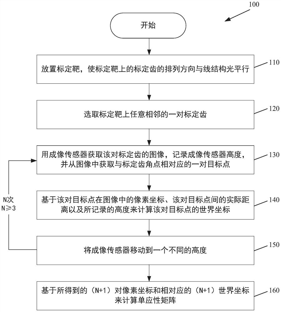
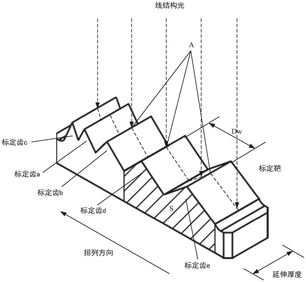
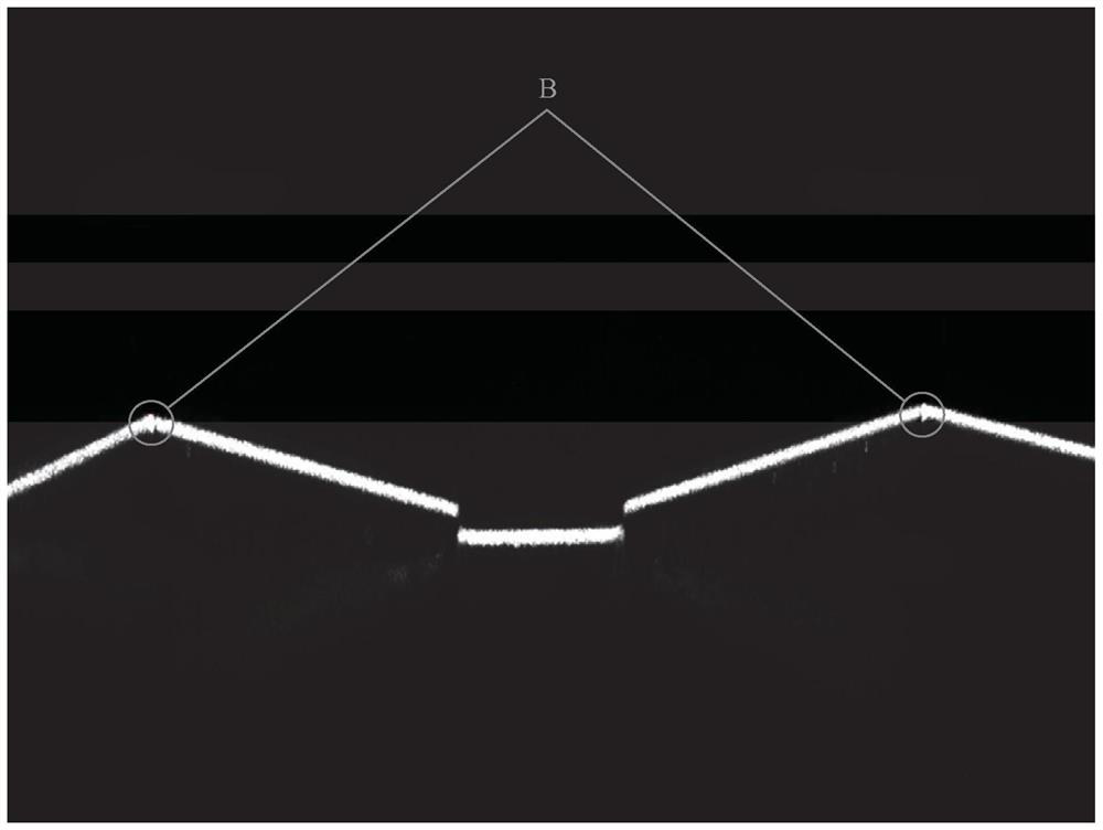
The invention relates to a line structured light imaging calibration method, a calibration system, a calibration target and a measurement system using the calibration target. The calibration method comprises the following steps: a, placing a calibration target so that the arrangement direction of calibration teeth on the calibration target is parallel to the line structure light; b, selecting any pair of adjacent calibration teeth on the calibration target; c, an image of the pair of calibration teeth is obtained through an imaging sensor, the height of the imaging sensor in the Z-axis direction perpendicular to the placement plane of the calibration target is recorded, and the image comprises a pair of angular points, irradiated by the line structured light, of the pair of calibration teeth serving as a pair of target points; d, world coordinates of the pair of target points are calculated based on the pixel coordinates of the pair of target points in the image, the actual distance between the pair of target points and the recorded height; e, the imaging sensor is moved to different heights N times in the Z-axis direction, the steps c-d are executed again after each time of movement, and N is larger than or equal to 3; and f, calculating a homography matrix based on the (N + 1) pair pixel coordinates and the corresponding (N + 1) pair world coordinates obtained in the steps c-e.

Description

technical field [0001] The invention relates to the technical field of visual measurement, and more particularly to a calibration method, a calibration system, a calibration target and a measurement system using the line structured light imaging. Background technique [0002] The visual measurement technology based on line structured light is a three-dimensional information non-contact measurement technology based on the measurement principle of laser triangulation. Dimensional detection and other aspects have broad application prospects. When using this technology to measure the three-dimensional information of the object, the structured light profile representing the shape of the object is generated by projecting line structured light onto the object surface, and the imaging system (such as a camera) acquires image information containing the structured light profile from a certain angle. If the relative positional relationship between the image information and the structu...

Claims


Application Information

Patent Timeline
Patent Type & Authority Applications(China)
IPC IPC(8): G06T7/80G06F17/16
CPCG06T7/85G06F17/16G06T2207/30244
Inventor 万章沈文立徐超
Owner 上海柏楚电子科技股份有限公司
Learn More