
Anti-falling mechanism of security inspection robot

An inspection robot and anti-falling mechanism technology, applied in the field of security, can solve the problems of aggravating the dumping force, the wear of the abutting block, and the failure to prevent the falling, etc., to achieve strong practicability, improve the anti-dumping effect, and improve the self-straining performance. Effect

Pending Publication Date: 2022-03-25
吴国均
View PDF1 Cites 0 Cited by
  • Summary
  • Abstract
  • Description
  • Claims
  • Application Information

AI Technical Summary

Problems solved by technology

[0004] If the block in the existing device needs to achieve the purpose of preventing falling, it needs to be set at a height that is relatively close to the ground. Although it does not hinder normal driving, it is easy to cause friction between the block and the ground when the road surface is uneven, which will make the block Gradually wear and tear and can't have anti-fall effect, moreover, the steel ball that is provided with in this device will slide toward the other side of impact point after this device is hit, although avoided this device to topple over to one side of impact point like this , but the gravity of the steel ball will aggravate the tilting force of the device towards the opposite direction of the impact point. In view of this, we propose an anti-falling mechanism for the security inspection robot

Method used


Image

  • Anti-falling mechanism of security inspection robot
  • Anti-falling mechanism of security inspection robot
  • Anti-falling mechanism of security inspection robot

Examples


Embodiment Construction

[0032] The invention provides a technical solution:

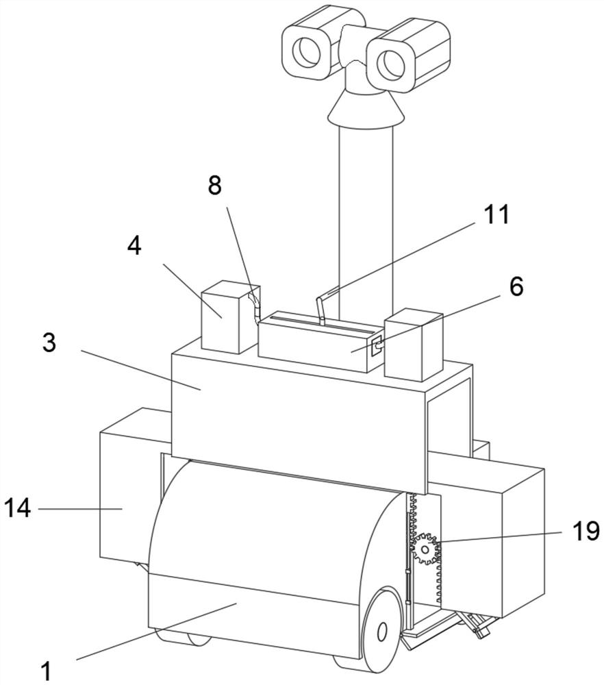
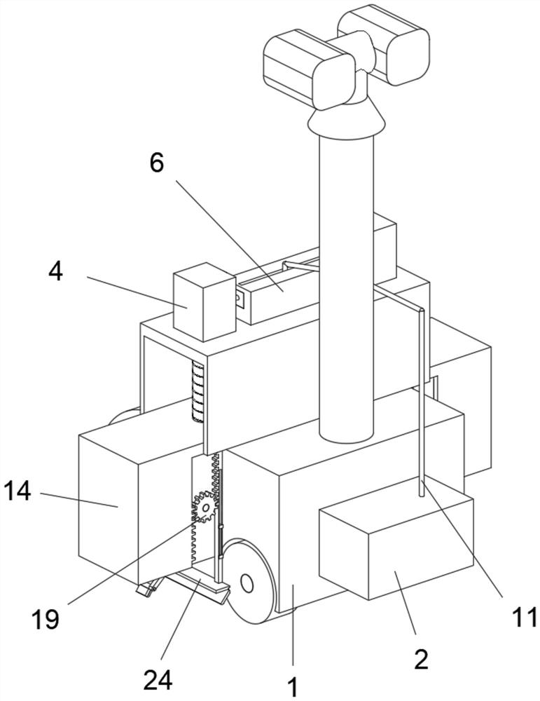
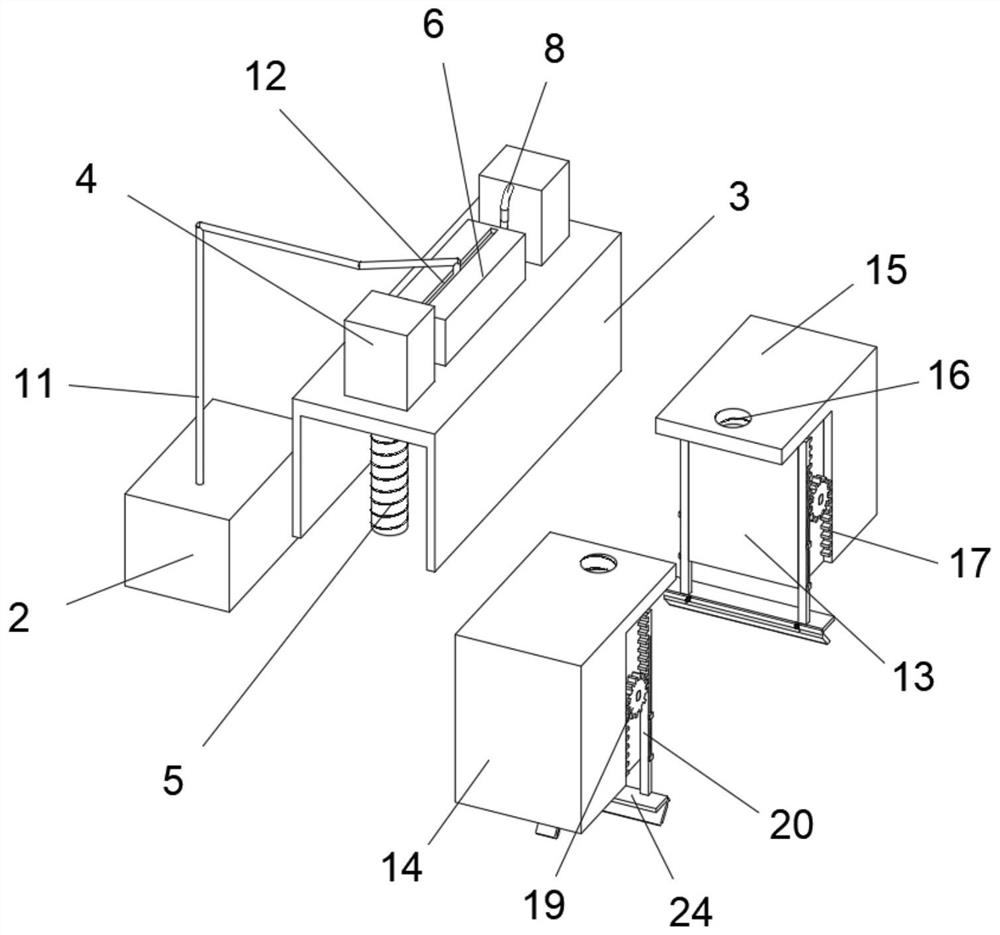
[0033] An anti-falling mechanism of a security inspection robot, such as figure 1 As shown, it includes a main body 1 of the inspection robot; an anti-fall device arranged inside the main body of the inspection robot; and a driving device arranged above the anti-fall device.

[0034] Specifically, such as Figure 1-5As shown, the driving device includes a power supply box 2, a fixed seat 3 and a balance box 6. The power supply box 2 is fixed in the middle of the rear wall of the main body of the inspection robot 1, and the fixed seat 3 is fixed in the middle of the top surface of the main body of the inspection robot 1. The fixed seat 3 Two motors 4 are symmetrically fixed on both sides of the top surface. The output end of the motor 4 extends through the top surface of the fixing base 3 to the lower part and is coaxially fixedly connected with a threaded rod 5. A balance box 6 is arranged between the two motors 4 for bala...


PUM


Abstract

The invention discloses an anti-falling mechanism of a security inspection robot, and belongs to the technical field of security. An anti-falling mechanism of a security inspection robot comprises an inspection robot body, a fixing base is fixedly arranged in the middle of the top face of the inspection robot body, two motors are symmetrically and fixedly arranged on the two sides of the top face of the fixing base, extension springs are fixedly arranged between the outer side wall of a sliding block and the outer side wall of a sliding groove, and a connecting plate A is hinged to the inner side end of the bottom face of a moving base; a through groove is formed in the bottom surface of the box body opposite to the connecting plate A, the lower end of the connecting plate A penetrates through the through groove, extends to the outside and is hinged with a connecting plate B, a rubber pad is fixedly arranged on the bottom surface of the connecting plate B, a cavity is formed in the top surface of the rubber pad, and a plurality of compression springs are fixedly arranged between the bottom surface of the cavity and the bottom surface of the connecting plate B in a matrix arrangement structure. According to the device, the toppling condition can be automatically judged, the problem of damage caused by friction between the supporting structure and the ground due to slight unevenness of the ground is prevented, and the autonomous strain performance of the device is improved.

Description

technical field [0001] The invention relates to the field of security technology, more specifically, to an anti-falling mechanism of a security inspection robot. Background technique [0002] Security can be understood as an acronym for "safety protection", that is, to prepare and protect to deal with attacks or avoid victims, so that the protected object is in a safe state without danger, inviolability, and accidents. There are three forms of protection: air defense, civil air defense, and technical defense. Security engineering is the process of using modern technology to achieve security protection. Security products are equipment that serve security engineering. With the rapid development of intelligent robots, they are now stored in large areas. In the working environment, security inspection robots are often used for security operations. [0003] After retrieval, the patent with the publication number CN111890417A discloses an anti-falling mechanism of a security insp...

Claims


Application Information

Patent Timeline
Patent Type & Authority Applications(China)
IPC IPC(8): G07C1/20
CPCG07C1/20
Inventor 吴国均
Owner 吴国均
Learn More