
Circuit breaker

A circuit breaker and arc extinguishing chamber technology, applied in the field of circuit breakers, can solve the problem that the output shaft of the mechanism and the crank arm rotating shaft of the arc extinguishing chamber cannot be connected in a transmission manner.

Pending Publication Date: 2022-03-25
PINGGAO GRP
View PDF13 Cites 0 Cited by
  • Summary
  • Abstract
  • Description
  • Claims
  • Application Information

AI Technical Summary

Problems solved by technology

[0005] The object of the present invention is to provide a circuit breaker to solve the technical problem in the prior art that the mechanism output shaft of the circuit breaker operating mechanism and the crank arm shaft of the arc extinguishing chamber cannot be connected in space when they intersect in space

Method used


Image

  • Circuit breaker
  • Circuit breaker
  • Circuit breaker

Examples


specific Embodiment 1

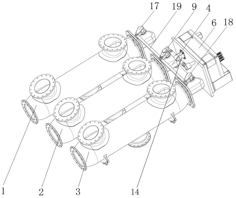
[0040] The structure of the circuit breaker provided in this embodiment is as follows figure 1 As shown in the figure, it includes A-phase arc-extinguishing chamber 1, B-phase arc-extinguishing chamber 2 and C-phase arc-extinguishing chamber 3. In order to drive the arc-extinguishing chamber to perform opening and closing actions, the end of each phase arc-extinguishing chamber is also provided with a driving mechanism, which drives the arc-extinguishing chamber. The mechanism is connected with the rod of the corresponding arc extinguishing chamber, so as to drive the rod action of the arc extinguishing chamber through the action of the driving mechanism, so as to realize the opening and closing of the arc extinguishing chamber, and then realize the opening and closing of the circuit breaker.

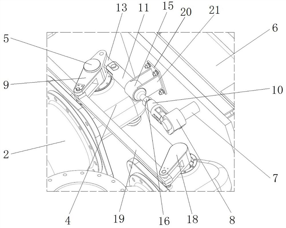
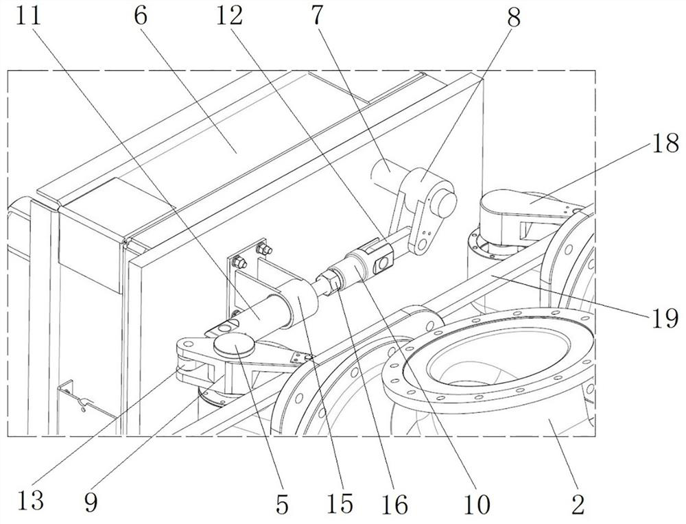
[0041] Specifically, taking the B-phase arc-extinguishing chamber 2 as an example, its driving mechanism includes a hinged arm box 4 and a hinged arm rotating shaft 5 arranged at the end...

specific Embodiment 2

[0050] The specific embodiment 2 of the circuit breaker provided by the present invention is mainly different from the embodiment 1 in that: in the embodiment 1, the sliding member and the guide seat are fitted by a socket. In this embodiment, for the guiding and matching manner of the guide seat and the sliding member, a guide groove is provided on one of the guide seat and the sliding member, and a sliding block matched with the guide groove is provided on the other one.

specific Embodiment 3

[0051] The specific embodiment 3 of the circuit breaker provided by the present invention is mainly different from the embodiment 1 in that: in the embodiment 1, the guide seat is fixed on the housing of the operating mechanism. In this embodiment, the guide seat is fixed on the arc extinguishing chamber. Of course, in other embodiments, a mounting base independent of the arc extinguishing chamber and the operating mechanism may also be provided to fix the guide seat.


PUM


Abstract

The invention belongs to the field of high-voltage switch equipment, and particularly relates to a circuit breaker which comprises an operating mechanism and a corresponding arc extinguish chamber, a mechanism output shaft of the operating mechanism and a crank arm rotating shaft of the corresponding arc extinguish chamber are arranged in a crossed mode in space, and the circuit breaker further comprises a guide seat fixedly arranged relative to the operating mechanism. A sliding piece is assembled on the guide seat along a straight line in a guiding manner; a first crank arm is arranged on the mechanism output shaft, the two ends of a first connecting piece are hinged to the first crank arm and a sliding piece, and the guide seat, the sliding piece, the first crank arm and the first connecting piece form a first crank sliding block mechanism, so that the rotating action of the mechanism output shaft can be converted into the linear action of the sliding piece; a second crank arm is arranged on the crank arm rotating shaft, the two ends of the second connecting piece are hinged to the second crank arm and the sliding piece respectively, and the guide base, the sliding piece, the second crank arm and the second connecting piece form a second crank sliding block mechanism, so that the linear action of the sliding piece can be converted into the rotating action of the crank arm rotating shaft.

Description

technical field [0001] The invention belongs to the field of high-voltage switchgear, in particular to a circuit breaker. Background technique [0002] The high-voltage switch is an important device in the high-voltage transmission line, which is used to control the on-off of the high-voltage transmission line. Structurally, the high-voltage switch mainly includes a circuit breaker, and the circuit breaker includes an arc-extinguishing chamber and an operating mechanism that drives the arc-extinguishing chamber to perform opening and closing actions. brake. [0003] The power transmission modes between the operating mechanism of the conventional circuit breaker and the corresponding arc extinguishing chamber mainly include the direct connection type and the plane link type. Among them, the direct-connected type is commonly used in hydraulic operating mechanisms, and the push rod of the hydraulic operating mechanism is directly connected to the direct-acting pull rod of the...

Claims


Application Information

Patent Timeline
Patent Type & Authority Applications(China)
IPC IPC(8): H01H73/18H01H71/10
CPCH01H73/18H01H71/10
Inventor 惠勇锋赵莉谭盛武韩国辉刘宇何保营李美荣宋广民郭良超牛平凯路智远许家源雷琴尹浩田李云龙闫飞越
Owner PINGGAO GRP
Learn More