A mobile power charging device capable of automatic storage

A mobile power supply and charging device technology, which is applied in the direction of battery circuit devices, circuit devices, clamping/extracting devices, etc., can solve the problems of size change, damage or large deformation of mobile power sources, and reduce the charging safety of mobile devices, etc., to achieve increased Effects of friction, widening of the application range, and reduction of the chance of deformation

Active Publication Date: 2022-04-29
SHENZHEN JOWAY POWER SUPPLY
View PDF9 Cites 0 Cited by
  • Summary
  • Abstract
  • Description
  • Claims
  • Application Information

AI Technical Summary

Problems solved by technology

[0003] The Chinese utility model patent with the publication number CN208868534U in the prior art discloses a mobile power supply storage device, including a storage box. A storage slot is provided on the top side of the storage box, and two storage slots are movably installed on the inner wall of the bottom side of the storage slot. The baffle, the storage tank is equipped with a rotating adjustment structure, which is connected with the push handle located outside the storage box to adjust the distance between the baffles, so as to adapt to different sizes of mobile power supplies. The use range of this device is obtained. Expand, but this device also has the following two problems: one is that the distance between the baffles is only used to adapt to the size change of the mobile power supply under horizontal placement, that is, the mobile power supply can only be placed horizontally; the other is a single storage slot Only one mobile power supply can be placed inside. When multiple mobile power supplies need to be stored, multiple mobile power supplies can only be stacked in one storage slot. When the device is moved as a whole or when an external force collides with the device, the mobile power supply will be damaged or deformed In addition, if there are impurities such as dust and fine particles attached to the charging port of the mobile power supply, the use effect of the mobile power supply will be directly affected, and the charging safety of the mobile device will also be reduced.

Method used


Image

  • A mobile power charging device capable of automatic storage
  • A mobile power charging device capable of automatic storage
  • A mobile power charging device capable of automatic storage

Examples


Embodiment Construction

[0030] The following will clearly and completely describe the technical solutions in the embodiments of the present invention with reference to the accompanying drawings in the embodiments of the present invention. Obviously, the described embodiments are only some, not all, embodiments of the present invention. Based on the embodiments of the present invention, all other embodiments obtained by persons of ordinary skill in the art without making creative efforts belong to the protection scope of the present invention.

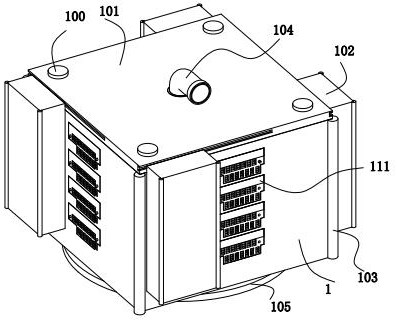
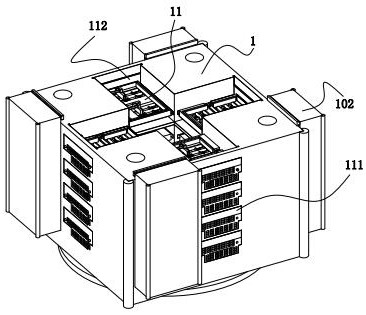
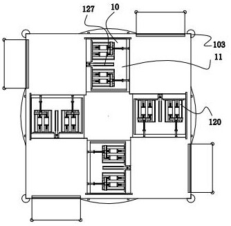
[0031] refer to figure 1 , figure 2 with image 3 , a mobile power charging device that can be stored automatically, including a storage box 1, and storage slots are opened on the side walls of the storage box 1 at equal distances from top to bottom, and a storage unit 10 is snapped into the storage slot. The upper end of the box 1 is connected with a top cover 101 through connecting bolts 100 , and the connecting bolts 100 are located at four right-angle e...


PUM


Abstract

The present invention relates to the technical field of mobile power supply, in particular to a charging device for mobile power supply that can be stored automatically, including a storage box. The side walls of the storage box are provided with storage slots at equal distances from top to bottom, and the storage slots are locked A storage unit is connected, and the upper end of the storage box is connected with a top cover through connecting bolts, and the connecting bolts are located at right-angle ends around the top cover. The storage box in the present invention can realize the independent storage of multiple mobile power supplies at the same time, and simultaneously place the mobile power supplies horizontally On the basis of the storage unit, the storage unit can be adaptively adjusted according to the size of the mobile power supply, that is, the storage unit can be adapted to different sizes of mobile power supplies, thereby expanding the use range of the storage box, and the vertical storage unit in the storage unit can also be placed according to the vertical The horizontal, vertical and height dimensions of the lower mobile power supply are adaptively adjusted, thereby further expanding the application range of the storage box.

Description

technical field [0001] The invention relates to the technical field of mobile power sources, in particular to a charging device for mobile power sources that can be stored automatically. Background technique [0002] A mobile power supply is a portable charger that can be carried by individuals and can store electric energy by itself, mainly for charging consumer electronic products such as handheld mobile devices. [0003] The Chinese utility model patent with the publication number CN208868534U in the prior art discloses a mobile power supply storage device, including a storage box. A storage slot is provided on the top side of the storage box, and two storage slots are movably installed on the inner wall of the bottom side of the storage slot. The baffle, the storage tank is equipped with a rotating adjustment structure, which is connected with the push handle located outside the storage box to adjust the distance between the baffles, so as to adapt to different sizes of ...

Claims


Application Information

Patent Timeline
Patent Type & Authority Patents(China)
IPC IPC(8): H02J7/00H05K7/14H05K5/02H05K7/20B01D46/10B08B5/04F16F15/04
CPCH02J7/0042H05K7/1411H05K5/0213H05K5/0217H05K7/2089H05K7/20127B01D46/10B08B5/04F16F15/04
Inventor 邱才燕赖华英赖庆赖建明梁金朝
Owner SHENZHEN JOWAY POWER SUPPLY
Why Eureka
Try Eureka