

Cooking utensil
A technology of cooking utensils and cooking chambers, applied in the field of kitchen utensils, can solve the problems of loss of nutrient soup, inability to remove grease, inedibility, etc., and achieve the effect of rapid collection
- Summary
- Abstract
- Description
- Claims
- Application Information
AI Technical Summary
Problems solved by technology
Method used
Image

Examples
Embodiment 1
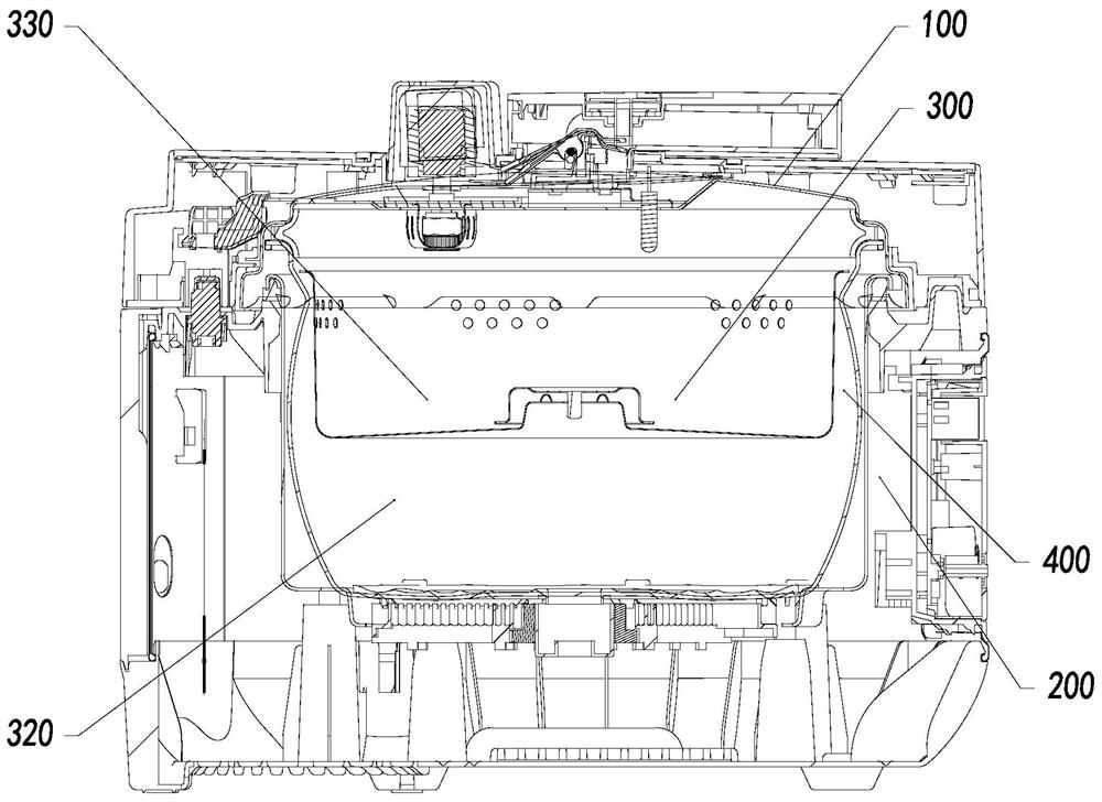
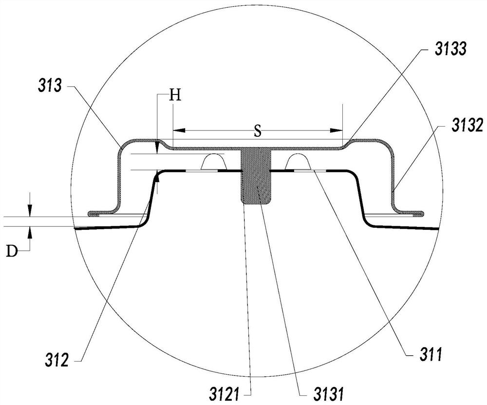
[0040] The present invention provides a cooking instrument, such as Figure 1-5 As shown, including the pot body 200 and the pot 100, the pot 100 is bonded to form the cooking chamber 400 on the pot body 200, and the cooking chamber 400 is provided with a collecting pan 300 to separate the cooking cavity 400 to form a lower cooking area 320 and The upper oil assembly 310; the oil filter assembly 310 is provided, and the oil filter assembly 310 is provided with a liquid hole 311 for exchange the soup liquid in the cooking area 320 and the oil collecting zone 330; The liquid hole 311 can be provided with a plurality of soup liquids in the cooking zone and the oil collecting zone. The oil filter assembly 310 is mounted with the oil filter 300 such that the soup liquid in the cooking chamber 400 is filtered to the oil fat in the soup liquid 300 by the bending flow; the oil filter assembly 310 cooperates with the oil filter 300 The height of the flow passage at the location is not highe...
Embodiment 2
[0048] Such as Figure 6-8 As shown, in the present embodiment, the boss 312 is detachable to the cover plate 313 to facilitate the deep cleaning of the oil filter assembly 310; the outer side wall of the boss 312 is provided with a barrel 3123, and the inner side wall of the cover 313 is provided. Card buckle 3134; barrier buckle 3123 cooperates with the clamped buckle 3134 to stop the block 313 to disengage the boss. By barrier buckle 3123 and the engagement of the cartridge 3134 to stop the block 312, the structure is simple, the disassembly is convenient, easy to clean, and the installation is convenient.
[0049]The bottom surface of the collecting disc 300 is provided with a support pad 350, a vertical projection of the bottom edge of the side wall 3132 is located on the support pad 350; the height of the support pad 350 is D2, 1 mm ≤ D2 ≤ 410 mm. By providing the support pad 350 such that the bottom edge of the side wall 3132 is placed on the support pad 350, and the height ...
Embodiment 3
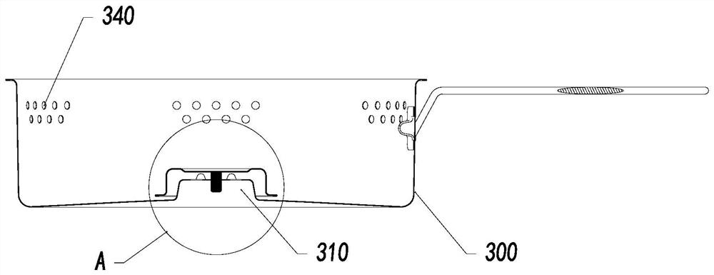
[0053] Such as Figure 7 As shown, the oil disc 300 can be disposed on the inner side wall of the pot body 200 to achieve the placement of the concentrating pan 300, and of course the concentrating pan 300 can also be placed in a pot such as a pot of the pot body 200. The upper portion of the sidewall of the collecting disc 300 has an air hole 340. Since a large amount of steam is generated during the cooking, the concentrating plate 300 is placed in the cooking chamber to prevent thermal steam from jacking up the oil tray 300 or causing the set oil disc 300 to install unstable, and sets an air hole. 340. The thermal steam in the cooking chamber 400 can be circulated by an air hole 340, thereby ensuring the stabilizing card of the collector plate 300.
[0054] And the air hole 340 is distributed with a plurality of groups, evenly at the upper portion of the side wall of the phiston 300. The overvisor 340 is distributed over the upper portion, preventing the soup liquid in the cooki...
PUM
 Abstract
Description
Claims
Application Information