Selective laser melting forming method for reducing residual stress of thin-wall part in situ

A technology of selective laser melting and residual stress, applied in the field of additive manufacturing, it can solve the problems of SLM forming failure, cracking, part warpage, etc., to reduce residual stress, reduce competition, and improve the success rate.

Active Publication Date: 2022-03-29
CHONGQING INST OF GREEN & INTELLIGENT TECH CHINESE ACADEMY OF SCI +1
View PDF7 Cites 2 Cited by
  • Summary
  • Abstract
  • Description
  • Claims
  • Application Information

AI Technical Summary

Problems solved by technology
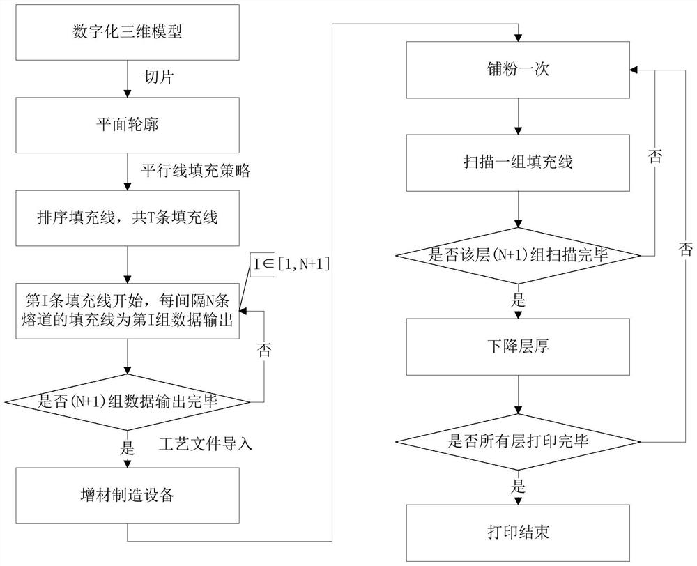
However, residual stress is easily generated during the SLM forming process, leading to defects such as warping, deformation, and cracking of parts, which greatly results in the failure rate of SLM forming and severely limits the development of SLM technology.
[0004] The existing main methods for reducing the residual stress of thin-walled parts formed by selective laser melting include heat treatment of formed parts, remelting, and adding supports, etc., but they still cannot solve the warping, deformation, and cracking caused by residual stress in the manufacturing process of thin-walled parts. And other issues

Method used


Image

  • Selective laser melting forming method for reducing residual stress of thin-wall part in situ
  • Selective laser melting forming method for reducing residual stress of thin-wall part in situ
  • Selective laser melting forming method for reducing residual stress of thin-wall part in situ

Examples


Embodiment Construction

[0024] Embodiments of the present invention are described below through specific examples, and those skilled in the art can easily understand other advantages and effects of the present invention from the content disclosed in this specification. The present invention can also be implemented or applied through other different specific implementation modes, and various modifications or changes can be made to the details in this specification based on different viewpoints and applications without departing from the spirit of the present invention. It should be noted that the diagrams provided in the following embodiments are only schematically illustrating the basic concept of the present invention, and the following embodiments and the features in the embodiments can be combined with each other in the case of no conflict.

[0025] Wherein, the accompanying drawings are for illustrative purposes only, and represent only schematic diagrams, rather than physical drawings, and should...


PUM


Abstract

The invention relates to a selective laser melting forming method for reducing residual stress of a thin-wall part in situ, and belongs to the technical field of additive manufacturing. The effect of reducing the residual stress of the thin-wall part in the printing process is achieved by controlling the single-layer powder laying frequency and the filling line scanning sequence. Slicing software is used for slicing and layering the three-dimensional model to generate an outline, filling lines of the cross section of the outline are sequenced, the filling lines at the interval of N melting channels are divided into one group, powder is laid on each layer for multiple times during printing, and only one group of filling lines is scanned after powder is laid every time. Sufficient metal powder is provided for each melting channel through filling line grouping scanning and multiple times of powder laying, so that the competition of adjacent filling lines for powder around the melting channels in the melting process is reduced, and the residual stress of the selective laser melting forming thin-wall part is reduced. The problems of warping and deformation of the thin-wall part caused by residual stress in the forming process can be effectively controlled, so that the forming rate of the selective laser melting formed thin-wall part is improved.

Description

technical field [0001] The invention belongs to the technical field of additive manufacturing, and relates to an area-selective laser melting forming method for reducing the residual stress of thin-walled parts in situ. Background technique [0002] Selective Laser Melting (SLM) additive manufacturing technology is a metal rapid prototyping method based on the principle of "discrete-accumulation". Layer and set the filling strategy, the software exports the process data to the process file, and the additive manufacturing equipment controls the laser beam to selectively melt each layer of metal powder material by analyzing the scanning path in the process file, and accumulates layer by layer for high performance and high density 3D parts. [0003] SLM technology has the advantages of short processing cycle and the ability to process metal parts with arbitrary complex shapes and structures. It can manufacture complex thin-walled parts that cannot be produced by traditional pr...

Claims


Application Information

Patent Timeline
IPC IPC(8): B22F10/28B22F10/31B33Y10/00B33Y80/00
CPCB22F10/28B22F10/31B33Y10/00B33Y80/00Y02P10/25
Inventor 吴文杰张祺范树迁刘基权马红林魏文侯王林志
Owner CHONGQING INST OF GREEN & INTELLIGENT TECH CHINESE ACADEMY OF SCI
Why Eureka
Try Eureka