Surface derusting and polishing device for metal bar machining

A polishing device and metal rod technology, which is applied in metal processing equipment, grinding/polishing safety devices, grinding drive devices, etc., can solve the problems of metal rod polishing, slowing down the speed of metal rods, and the thickness of metal rods cannot be polished. , to achieve the effect of improving stability, speeding up and improving uniformity

Pending Publication Date: 2022-03-29
徐州锌浩精密机械科技有限公司
View PDF7 Cites 0 Cited by
  • Summary
  • Abstract
  • Description
  • Claims
  • Application Information

AI Technical Summary

Problems solved by technology

[0003] At present, the existing surface derusting and polishing device for metal rod processing still has some deficiencies, for example; the existing metal rod processing surface derusting and polishing device cannot automatically shape and output the metal rod before polishing, and the operation The personnel need to transport the metal rods in person. When the outer surface of the metal rod is polished, the operator needs to manually change the surface, which slows down the speed of the metal rod polishing and reduces the uni...

Method used


Image

  • Surface derusting and polishing device for metal bar machining
  • Surface derusting and polishing device for metal bar machining
  • Surface derusting and polishing device for metal bar machining

Examples


Embodiment Construction

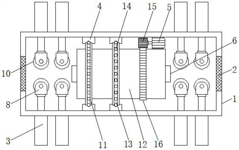
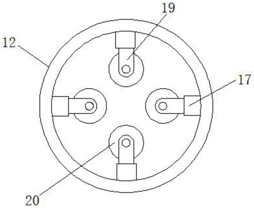
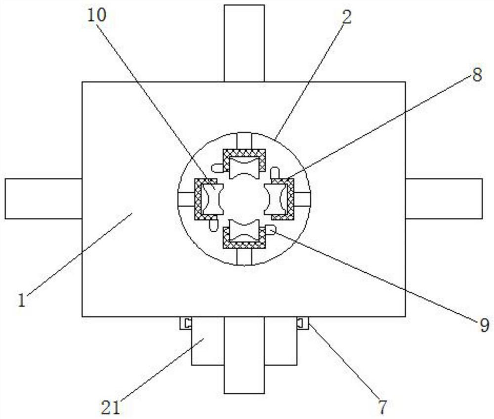
[0023] see Figure 1-Figure 4 , the present invention provides a technical solution: a surface derusting and polishing device for metal rod processing, including a device body 1, and the device body 1 is provided with an inlet and outlet trough 2, an electric push rod 3, and an arc-shaped limiting plate 4 , drive motor 5, feeding chute 6 and connecting plate 7, the inlet and outlet chute 2 are symmetrically arranged on the left and right sides of the device body 1, and the electric push rod 3 is fixedly connected to the outer surface of the device body 1 On the left and right sides, the arc-shaped limiting plate 4 is fixedly connected to the inner wall of the device body 1, the drive motor 5 is fixedly connected to the inner wall of the device body 1, and is located on the inner wall of the arc-shaped limiting plate 4. On the right side, the chute 6 runs through the bottom inside the device body 1, and the connecting plate 7 is fixedly connected to the bottom outside the devic...


PUM


Abstract

The surface derusting and polishing device for metal bar machining structurally comprises a device body, the device body is provided with feeding and discharging grooves, an electric push rod, an arc-shaped limiting plate, a driving motor, a discharging groove and a connecting plate, and the feeding and discharging grooves are symmetrically formed in the left side and the right side of the device body; the electric push rods are fixedly connected to the left side and the right side of the outer surface of the device body, the arc-shaped limiting plate is fixedly connected to the inner wall of the device body, the driving motor is fixedly connected to the inner wall of the device body and located on the right side of the arc-shaped limiting plate, and the discharging groove penetrates through the bottom of the interior of the device body. According to the polishing device, automatic shaping and outputting of the metal rods before polishing are achieved, the situation that operators convey the metal rods by themselves is avoided, the outer surfaces of the metal rods can be polished at a time, the polishing speed of the metal rods is increased, and the uniformity of the polishing device during polishing of the metal rods is improved.

Description

technical field [0001] The invention relates to the technical field of metal bar processing, in particular to a surface derusting and polishing device for metal bar processing. Background technique [0002] According to the patent 202010580602.4, a metal bar surface derusting and polishing device includes a machine body, a working chamber is arranged in the body, and the inner wall of the bottom side of the working chamber is fixed with left and right symmetrical connecting blocks, and the left connecting block A connecting cavity is arranged inside, and a suspension block is fixedly installed on the inner wall of the top side of the working cavity, and a derusting assembly for derusting metal rods is provided under the suspension block. When the device is working, the main friction can be made The metal rods are transported by the block and the left and right connecting blocks. The metal rods can be evenly derusted by the rotation of the connecting gear and the reciprocatin...

Claims


Application Information

Patent Timeline
IPC IPC(8): B24B27/033B24B41/00B24B41/04B24B41/06B24B47/12B24B47/22B24B55/12
CPCB24B27/033B24B41/005B24B41/06B24B47/22B24B41/04B24B47/12B24B55/12
Inventor 曾静
Owner 徐州锌浩精密机械科技有限公司
Why Eureka
Try Eureka