Supercharge Your Innovation With Domain-Expert AI Agents!

High-efficiency sewage treatment device

A sewage treatment device and high-efficiency technology, applied in water/sewage multi-stage treatment, water/sludge/sewage treatment, filtration treatment, etc., which can solve the problem of reducing the possibility of metal-rich water bodies and unfavorable efficient sewage treatment operations. and other problems to achieve the effect of ensuring conveying efficiency, facilitating separation, and ensuring contact area

Pending Publication Date: 2022-03-29
蚌埠市兄弟粮油食品科技有限公司
View PDF0 Cites 0 Cited by
  • Summary
  • Abstract
  • Description
  • Claims
  • Application Information

AI Technical Summary

Problems solved by technology

[0002] Sewage refers to the polluted water from life and production, which has lost its original function. Based on the concept of green environmental protection, in the existing technology, such as figure 1 As shown, the use of sewage treatment equipment to perform magnetic separation, filtration and separation operations on sewage reduces the possibility of metal-rich water. However, in this equipment, the water finally obtained in the collection tank still contains more Oil body, additional secondary separation operation is required in the follow-up, which is not conducive to the efficient operation of sewage treatment

Method used


Image

  • High-efficiency sewage treatment device
  • High-efficiency sewage treatment device
  • High-efficiency sewage treatment device

Examples


Embodiment 1

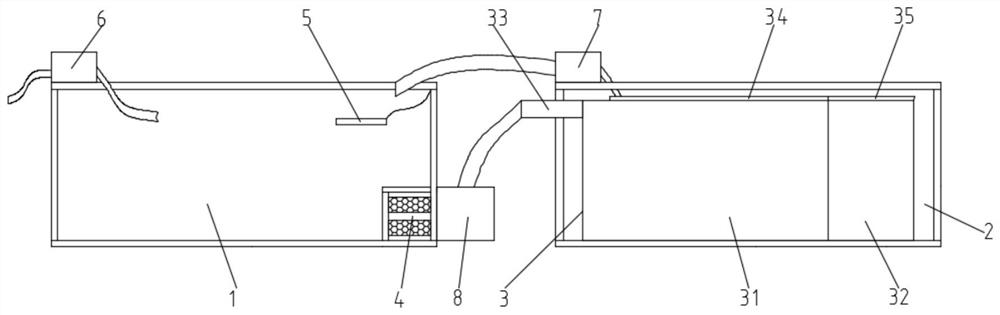
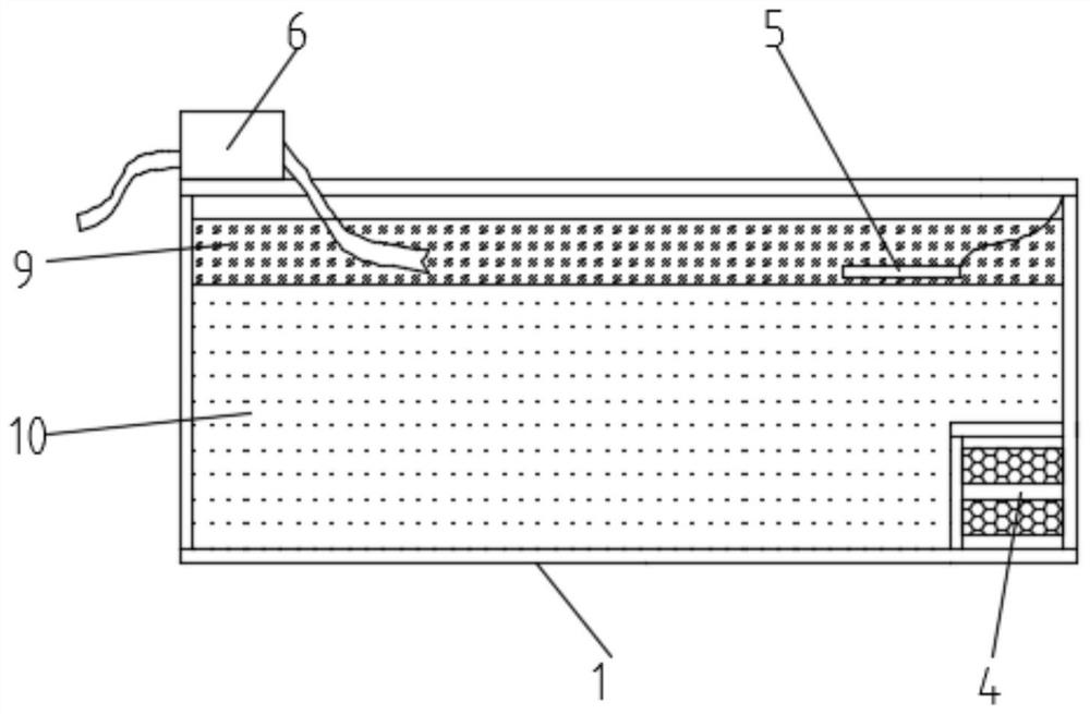
[0030] see figure 2 As shown, in the present invention, the inside of the oil-water separation box 1 is provided with an indicator circle 5, and an elastic pull cord is connected between the indicator circle 5 and the top inner wall of the oil-water separation box 1, wherein the density of the indicator circle 5 is greater than that of the oil-water separation box 1. density of the oil body 9, and the density of the indicator circle 5 is less than that of the water body 10, under the action of the elastic pull cord and the physical property factors of the indicator circle 5 itself, the indicator circle 5 sinks inside the oil body 9, and finally floats in the oil body 9. On the interface between body 9 and water body 10, start pump body one 6 again, when the oil body 9 that is positioned at the upper end of water body 10 is pumped out by the pump body one 6 that is provided with, indicator ring 5 will finally float on water body 10, by observing indication The floating conditi...

Embodiment 2

[0032] see figure 2 As shown, in the present invention, one side inner wall of the oil-water separation box 1 is provided with a first-level separation block 4, and a filter tank is provided on the outer surface of the first-level separation block 4, and a filter plate is clamped inside the filter tank, and the filter plate There are several filter holes arranged in a rectangular array on the top, and the inside of the first-level separation block 4 is provided with a cavity, and the whole is a hollow structure, that is, the front, rear and upper ends of the first-level separation block 4 are not separated from oil and water. A filter tank is provided on one side of the box body 1 where the inner wall is attached to one end shell, and the first-stage separation block 4 is provided to perform a first-stage filtration operation on the sewage, specifically, to remove the fixed residue with a particle size larger than the filter hole. For interception, the fixed residues that can...

Embodiment 3

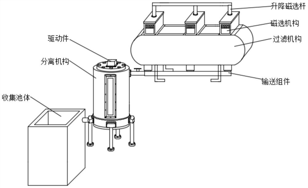
[0034] see image 3 - Figure 6 As shown, in the present invention, the separation mechanism includes a solid-liquid separation box 3, and the solid-liquid separation box 3 is composed of a filter box 31 and a buffer box 32 clamped on one side of the filter box 31, and the filter box 31 The other side of the filter box 31 is equipped with a liquid inlet pipe 33, one end of the liquid inlet pipe 33 penetrates to the outside of the collection box 2 and is connected with the output end of the pump body 6, and the upper end of the filter box 31 is fixed with a cover plate 34 by bolts , the upper end of the buffer box 32 is fixed with a cover plate 2 35 by bolts, and the inside of the filter box 31 is provided with several secondary separation blocks 39 arranged equidistantly. In the present invention, the inside of the filter box 31 is provided with There is a buffer plate 38 positioned at one side of the secondary separation block 39, and the inside of the filter box body 31 is ...


PUM


Abstract

The invention discloses a high-efficiency sewage treatment device which comprises an oil-water separation box body, a collection box body is arranged on one side of the oil-water separation box body, a separation mechanism is arranged in the collection box body, a second pump body is arranged at the upper end of the collection box body, and the output end of the second pump body penetrates into the oil-water separation box body. A first liquid outlet pipe is arranged on the outer surface of the oil-water separation box body, a third pump body connected with the first liquid outlet pipe is arranged on the outer surface of the oil-water separation box body, the output end of the third pump body is connected with the separation mechanism, a first pump body is arranged at the upper end of the oil-water separation box body, and the input end of the first pump body penetrates into the oil-water separation box body; according to the sewage treatment device, oil and water can be efficiently separated from sewage, the water and solid residues are subjected to multi-stage filtering operation, and finally the treated sewage meeting the emission standard is obtained.

Description

technical field [0001] The invention relates to the technical field of sewage treatment, in particular to a high-efficiency sewage treatment device. Background technique [0002] Sewage refers to the polluted water from life and production, which has lost its original function. Based on the concept of green environmental protection, in the existing technology, such as figure 1 As shown, the use of sewage treatment equipment to perform magnetic separation, filtration and separation operations on sewage reduces the possibility of metal-rich water. However, in this equipment, the water finally obtained in the collection tank still contains more For the oil body, an additional secondary separation operation is required in the follow-up, which is not conducive to the efficient operation of sewage treatment. [0003] Based on this, a new solution is proposed here. Contents of the invention [0004] The purpose of the present invention is to provide a high-efficiency sewage tre...

Claims


Application Information

Patent Timeline
IPC IPC(8): C02F9/02
CPCC02F1/001C02F1/40
Inventor 董其云于雷常同权路兴涛马顺杰张克
Owner 蚌埠市兄弟粮油食品科技有限公司
Features
  • R&D
  • Intellectual Property
  • Life Sciences
  • Materials
  • Tech Scout
  • Unparalleled Data Quality
  • Higher Quality Content
  • 60% Fewer Hallucinations
Learn More