Anti-collision buffering equipment for highway engineering maintenance
A buffer equipment and engineering technology, applied in the directions of roads, roads, road signs, etc., can solve the problems of safety threats in the working area in front of the vehicle, increase the buffer distance of the buffer car, and the length of the anti-collision buffer car, so as to achieve labor-saving and quick recovery and reduce collisions. the effect of the probability of
- Summary
- Abstract
- Description
- Claims
- Application Information
AI Technical Summary
Problems solved by technology
Method used
Image

Examples
no. 1 example
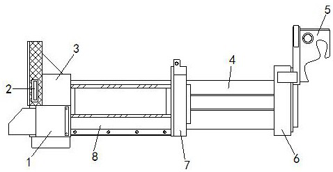
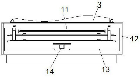
[0025] see Figure 1-Figure 4 , the present invention provides a technical scheme of anti-collision buffer equipment for highway engineering maintenance: its structure includes: front guide box device 1, warning sign 2, contact frame 3, first buffer zone 4, connecting frame device 5, frame plate 6, Rigid support frame 7, second buffer zone 8, the connecting frame device 5 is arranged above the frame plate 6 and locked with the frame plate 6, the front end of the frame plate 6 is provided with a first buffer zone 4, the first A rigid support frame 7 is provided at the front end of the buffer zone 4, and the rigid support frame 7 is locked to the first buffer zone 4, and a second buffer zone 8 is provided on the front side of the rigid support frame 7, and the second buffer zone A contact frame 3 is provided at the front end of the area 8, and a front guide box device 1 is provided below the contact frame 3. The front guide box device 1 is fastened with the contact frame 3, and ...
no. 2 example
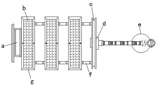
[0030] see Figure 5-Figure 6 , the present invention provides a technical scheme of anti-collision buffer equipment for highway engineering maintenance: its structure includes: the supporting bottom frame g includes a stress frame g1, a sleeve frame groove g2, and a matching wheel device g3, and the sleeve frame groove g2 is set Below the stress frame g1 and welded with the stress frame g1, the inner side of the sleeve frame groove g2 is locked with a mating wheel device g3.
[0031] The matching wheel device g3 includes a bearing frame g31, a movable hinge frame g32, a mounting frame g33, and a moving wheel g34. The moving wheel g34 is arranged on the inner side of the bearing frame g31 and is fastened with the bearing frame g31. The bearing The partition frame g31 is arranged under the installation frame g33, and the side of the installation frame g33 is locked with a movable hinge frame g32.
[0032] The main features of the present invention are: the stress frame g1 main...
PUM
 Abstract
Description
Claims
Application Information
 - Generate Ideas
- Intellectual Property
- Life Sciences
- Materials
- Tech Scout
- Unparalleled Data Quality
- Higher Quality Content
- 60% Fewer Hallucinations
Browse by: Latest US Patents, China's latest patents, Technical Efficacy Thesaurus, Application Domain, Technology Topic, Popular Technical Reports.
© 2025 PatSnap. All rights reserved.Legal|Privacy policy|Modern Slavery Act Transparency Statement|Sitemap|About US| Contact US: help@patsnap.com