Active magnetic bearing rotor falling protection method
A technology of active magnetic bearing and drop protection, applied in the field of magnetic levitation, to achieve the effect of simple cost and low cost
- Summary
- Abstract
- Description
- Claims
- Application Information
AI Technical Summary
Problems solved by technology
Method used
Image

Examples
Embodiment Construction
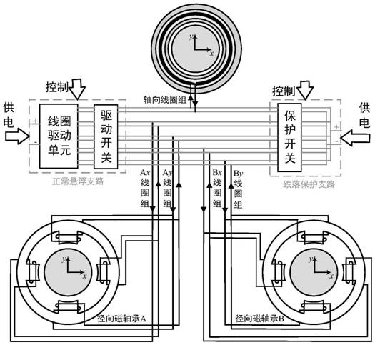
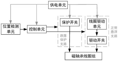
[0010] The invention relates to a method for protecting an active magnetic bearing rotor from falling. According to the detected state of the rotor, the magnetic bearing coil group can be controlled to be connected to the normal suspension branch or the drop protection branch, so as to realize the safe and stable operation of the rotor. It mainly includes: system power supply unit, position detection unit, control unit, normal suspension branch, drop protection branch and magnetic bearing coil group. The system power supply unit of the present invention includes filtering, rectifying and voltage conversion circuits, which provide corresponding stable DC voltages for the position detection unit, control unit, normal suspension branch and drop protection branch. The position detection unit of the present invention includes a distance sensor installed at two radial magnetic bearings to measure the position of the rotor in the two orthogonal directions x and y in the radial direct...
PUM
 Abstract
Description
Claims
Application Information