High-emission hub unit

A hub unit, rolling element technology, applied in the direction of hubs, casters, wheels, etc., can solve problems such as insufficient to allow sludge to leave the chamber, sludge retention trapped, unsatisfactory sealing components, etc.

Pending Publication Date: 2022-03-29
AB SKF
View PDF2 Cites 0 Cited by
  • Summary
  • Abstract
  • Description
  • Claims
  • Application Information

AI Technical Summary

Problems solved by technology

However, since this sealing system is axially symmetrical, the discharge on the underside may not be sufficient to allow sludge to leave the chamber
Consequently, the sludge remains trapped, leading to unsatisfactory operation of the seal assembly

Method used


Image

  • High-emission hub unit
  • High-emission hub unit
  • High-emission hub unit

Examples


Embodiment Construction

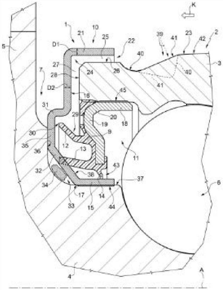
[0015] refer to figure 1 , 1 denotes a low friction sealing assembly, especially designed to be mounted on a hub unit 2 of a vehicle, the sealing assembly 1 of which forms an integral part of said unit during use. The description of this known solution as mentioned above is intended to help a better understanding of the embodiments of the present invention.

[0016] A hub unit 2 of a yet known type comprises: an outer ring 3, which is stationary ( / stationary) during use; an inner ring 4, which rotates during use around an axis A, which is also of both rings 3 and 4 an axis of symmetry; and at least one row of rolling elements 6 between an outer ring 3 and an inner ring 4 coaxial to each other; the ring 4 has a flanged end 5 opposite the outer ring 3 and for carrying the wheel.

[0017] The seal assembly 1 can be inserted into an annular gap ( / space / void) 7 defined between the rotating inner ring 4 of the hub 2 and the stationary outer ring 3 ( / stationary outer ring), and more...


PUM


Abstract

A hub unit (102) is provided with: a radially outer ring (103) which is stationary during use; a radially inner ring (104) that rotates during use; at least one row of rolling elements (6) interposed between the radially outer ring and the radially inner ring; and a seal assembly (101) interposed between the radially outer ring and the radially inner ring, the seal assembly cooperating with the radially outer ring or with the radially inner ring defining a shield of at least one labyrinth seal (22, 122). The labyrinth seal does not have circumferential symmetry, but comprises an upper part (22) and a lower part (122) with respect to the axis of symmetry (A) of the hub unit, and is provided with an angular interruption of a shield formed on the lower part of the labyrinth seal corresponding to the underside of the hub unit, the labyrinth seal is disposed within the seal assembly such that an outflow portion of the labyrinth seal from the labyrinth seal is increased, which facilitates gravitational discharge of contaminants present within the seal assembly.

Description

technical field [0001] The present invention relates to a high-drainage vehicle hub unit. In particular, the hub unit performs high emissions in the area of ​​the sealing assembly equipped with the rolling bearing of the hub unit. Background technique [0002] Seal assemblies, such as those described in US8303190 and US2012 / 0177315, intended to assemble the rolling bearing of the hub unit on the flange side supporting the wheel (so-called "outer" or "outboard") are made of so-called The "box" seal consists of a first annular shield (screen) and a second annular shield, the first annular shield and the second annular shield Have a generally L-shaped radial cross-section and are mounted facing each other so as to define an annular chamber between the shields, inside this annular chamber a series of sealing lips are arranged, these lips are mounted in a unit integral with one of the shields. Fixed on an annular gasket ( / gasket / gasket), normally the shield is intended to remai...

Claims


Application Information

Patent Timeline
IPC IPC(8): F16C33/78F16C33/80B60B27/00
CPCF16C33/7806F16C33/7826F16C33/805B60B27/00B60B27/0073F16J15/3264F16C33/7883F16C33/7886B60B2900/511F16C33/7889F16C33/7896F16C33/7823F16C2326/02B60B27/02B60B2900/211
Inventor 保罗·阿雷
Owner AB SKF
Why Eureka
Try Eureka