Electric control silicone oil clutch structure with separated magnetic circuits

A silicone oil clutch and electronic control technology, applied in the field of clutches, can solve the problems of easy deviation of clutch performance, large magnetic circuit loss, and non-brittle valve opening and closing, and achieve the effect of improving consistency, avoiding performance deviation and simple design.

Pending Publication Date: 2022-03-29
苏州奥沃汽车配件有限公司
View PDF0 Cites 0 Cited by
  • Summary
  • Abstract
  • Description
  • Claims
  • Application Information

AI Technical Summary

Problems solved by technology

[0002] At present, the traditional electronically controlled silicone oil clutch cannot avoid the design interference of the magnetic circuit in the design of the valve plate and the internal configuration design. The magnetic force must be transmitted through the valve plate to form a closed loop, which makes the structural design of the valve plate and the structural layout of the working chamber affected. The magnetic circuit is restricted, and the loss of the magnetic circuit is large. At the same time, because the magnetic circuit needs to pass through the valve plate, the valve plate is in a strong magnetic state, so that the opening and closing of the valve plate is not straightforward, resulting in easy deviation of the clutch performance.

Method used


Image

  • Electric control silicone oil clutch structure with separated magnetic circuits
  • Electric control silicone oil clutch structure with separated magnetic circuits
  • Electric control silicone oil clutch structure with separated magnetic circuits

Examples


Embodiment Construction

[0020] The preferred embodiments of the present invention will be described in detail below in conjunction with the accompanying drawings, so that the advantages and features of the present invention can be more easily understood by those skilled in the art, so as to define the protection scope of the present invention more clearly.

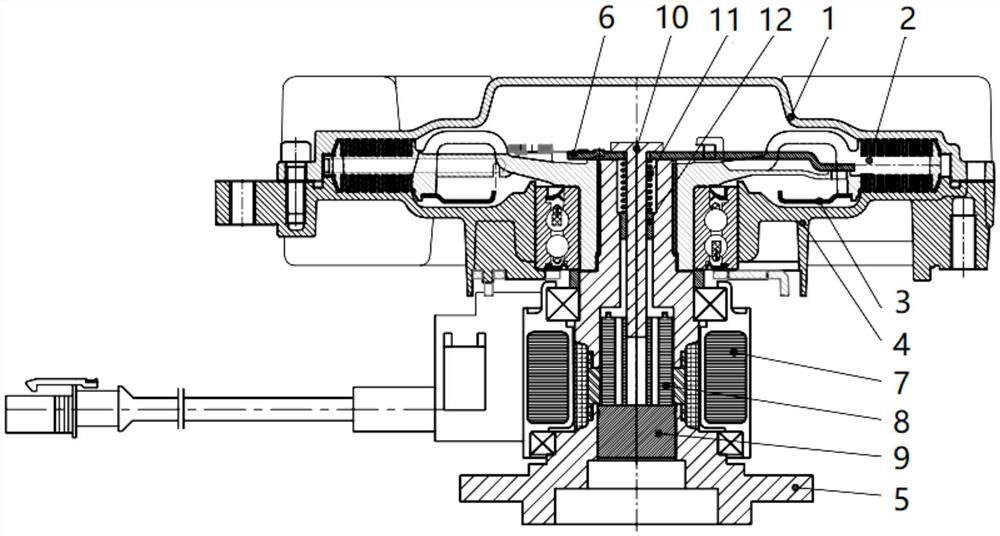
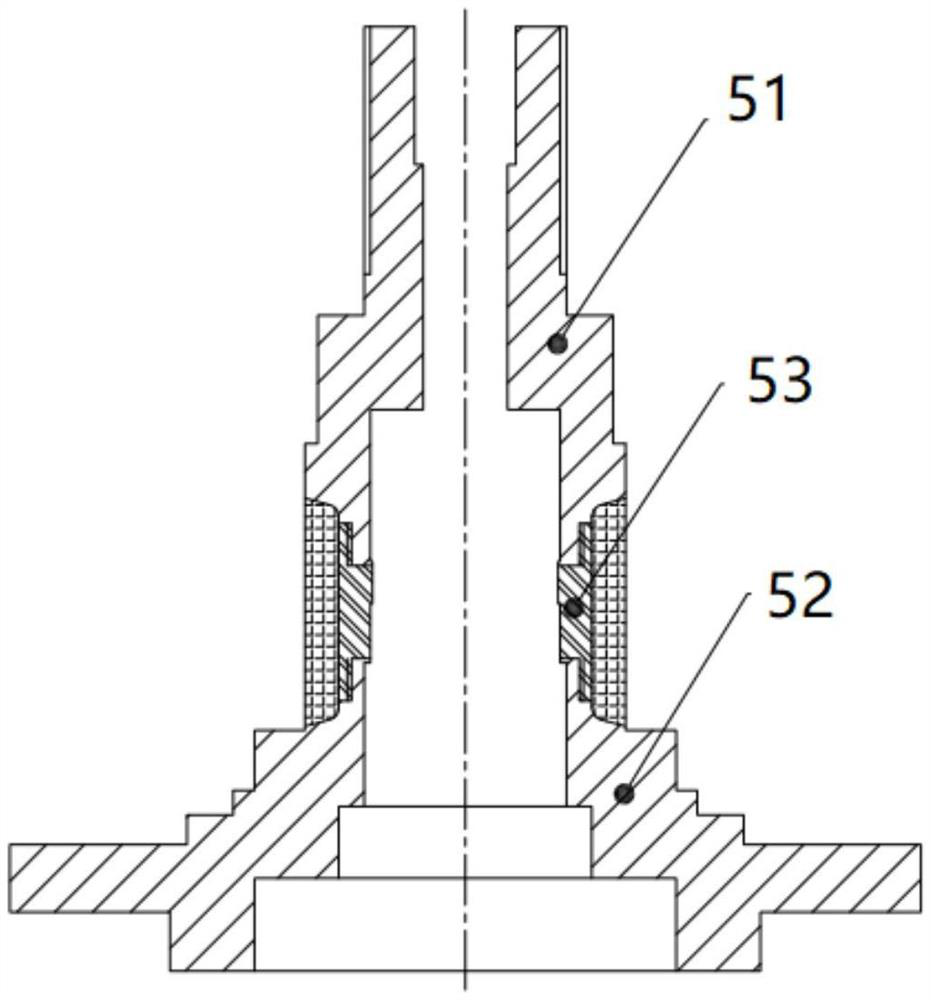
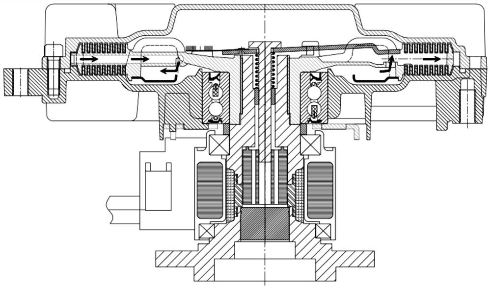
[0021] see Figure 1 to Figure 7 , this example includes:

[0022] An electronically controlled silicon oil clutch structure with magnetic circuit separation, including a front cover 1, a driving plate 2, a driven plate 3, a housing 4, a driving shaft 5 and a valve plate assembly 6, the front cover 1 is arranged on the housing 4 The upper end of the upper end, the active plate 2 is arranged between the housing 4 and the front cover 1, and the active plate 2, the housing 4 and the front cover 1 together form a working chamber, and a plurality of the driven plates 3 are respectively arranged on the The lower end of the active plate 2, and the acti...


PUM


Abstract

The invention discloses a magnetic circuit separated electric control silicone oil clutch structure which comprises a front cover, a driving plate, a driven plate, a shell, a driving shaft and a valve plate assembly. A sliding block, a sealing block and a piston rod are arranged in the driving shaft, and the sliding block is arranged at the upper end of the sealing block; the piston rod is arranged between the upper portions of the sliding blocks and extends upwards to be connected with the valve plate assembly, the periphery of the piston rod is sleeved with a spring and a copper sleeve, and the spring is located between the valve plate assembly and the copper sleeve. A magnetic circuit separation structure is adopted, the magnetic circuit and the valve plate assembly are independently separated, the structural design of the valve plate assembly and the structural layout of the working cavity are completely not limited by the magnetic circuit, the design is simpler and more convenient, meanwhile, the valve plate assembly is in a weak magnetic or non-magnetic state in the working process, opening and closing of the valve plate assembly are smoother, and the service life of the valve plate assembly is prolonged. And the performance deviation of the clutch caused by the switching stroke of the valve plate assembly and the residual magnetism intensity is avoided, and the consistency of products is improved.

Description

technical field [0001] The invention relates to the technical field of clutches, in particular to an electrically controlled silicon oil clutch structure for magnetic circuit separation. Background technique [0002] At present, the traditional electronically controlled silicone oil clutch cannot avoid the design interference of the magnetic circuit in the design of the valve plate and the internal configuration design. The magnetic force must be transmitted through the valve plate to form a closed loop, which makes the structural design of the valve plate and the structural layout of the working chamber affected. The magnetic circuit is restricted, and the loss of the magnetic circuit is large. At the same time, because the magnetic circuit needs to pass through the valve plate, the valve plate is in a strong magnetic state, so that the opening and closing of the valve plate is not straightforward, resulting in easy deviation of the clutch performance. Contents of the inve...

Claims


Application Information

Patent Timeline
IPC IPC(8): F16D35/00
CPCF16D35/00
Inventor 汤自知
Owner 苏州奥沃汽车配件有限公司
Why Eureka
Try Eureka