Self-lubricating speed reducer
A speed reducer and self-lubricating technology, which is applied in the direction of gear lubrication/cooling, mechanical equipment, transmission parts, etc., can solve the problems that affect the appearance of the product, the amount of lubricating oil supply cannot be adjusted, and the pipeline is densely covered, so as to ensure normal operation , beautiful appearance, stable and reliable operation
- Summary
- Abstract
- Description
- Claims
- Application Information
AI Technical Summary
Problems solved by technology
Method used
Image
Examples
Embodiment 1
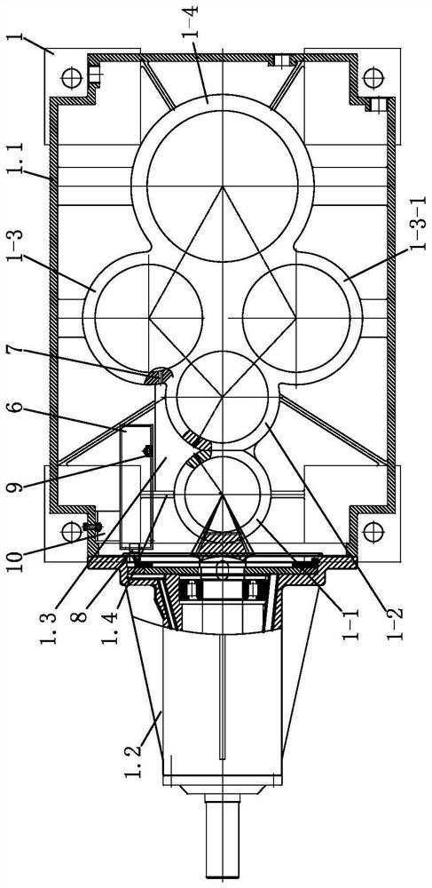
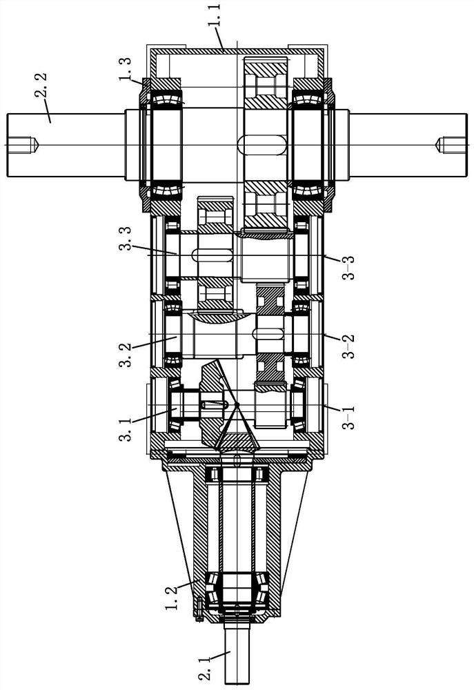
[0037] A self-lubricating reducer includes a casing 1, an input shaft 2.1, an output shaft 2.2, a transmission mechanism, an oil pump mechanism, and an oil separation mechanism.
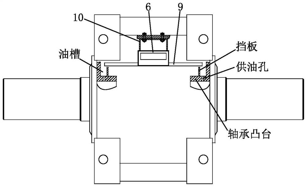
[0038] The input shaft and output shaft are rotatably positioned on the casing, the transmission mechanism is used to transmit power between the input shaft and the output shaft, the oil pump mechanism is driven by the input shaft to supply lubricating oil to the oil separation mechanism, and the oil separation mechanism It includes a first oil distribution mechanism and a second oil distribution mechanism, the first oil distribution mechanism distributes the lubricating oil to each transmission shaft of the transmission mechanism, and the second oil distribution mechanism distributes the lubricating oil to the input shaft.
[0039] The transmission mechanism adopts a four-stage reduction transmission, including a first transmission shaft 3.1, a second transmission shaft 3.2, and a third transmission ...
Embodiment 2
[0064] A self-lubricating reducer includes a casing 1, an input shaft 2.1, an output shaft 2.2, a transmission mechanism, an oil pump mechanism, a first oil separation mechanism, and a second oil separation mechanism. The reducer is a four-stage transmission orthogonal reducer, in which the input shaft and the output shaft are vertically arranged, and the output shaft is arranged parallel to the transmission shafts of the transmission mechanism.
[0065] Compared with embodiment 1, its difference is:
[0066] The oil pumping mechanism is driven by the first transmission shaft, on the first bearing boss ( Figure 13 Make the first stepped surface and the second stepped surface (omitted in the figure) on the shown 1-5), the pressure plate and the first stepped surface are fixed and an oil supply cavity is formed between the pressure plate and the second stepped surface, and the impeller is set on the oil supply cavity and fixed with the first transmission shaft, the opening 6-3...
Embodiment 3
[0070] A self-lubricating reducer includes a casing 1, an input shaft 2.1, an output shaft 2.2, a transmission mechanism, an oil pump mechanism, and a first oil separation mechanism. The reducer is a three-stage transmission parallel reducer ( Figure 14 shown), wherein the input shaft, output shaft, and transmission shafts of the transmission mechanism are arranged in parallel.
[0071] Compared with embodiment 1, its difference is:
[0072] The oil pump mechanism is driven by the input shaft, on the input shaft boss ( Figure 14 As shown in 1-6), the first stepped surface and the second stepped surface are made, the pressure plate is fixed to the first stepped surface and an oil supply cavity is formed between the pressure plate and the second stepped surface, and the impeller is arranged in the oil supply cavity and connected with the input The shaft is fixed, and the opening of the oil tank is located on the side (refer to Figure 13 The opening position of the pressure...
PUM
 Abstract
Description
Claims
Application Information
 - R&D
- Intellectual Property
- Life Sciences
- Materials
- Tech Scout
- Unparalleled Data Quality
- Higher Quality Content
- 60% Fewer Hallucinations
Browse by: Latest US Patents, China's latest patents, Technical Efficacy Thesaurus, Application Domain, Technology Topic, Popular Technical Reports.
© 2025 PatSnap. All rights reserved.Legal|Privacy policy|Modern Slavery Act Transparency Statement|Sitemap|About US| Contact US: help@patsnap.com


