
Charging robot and charging device for charging electrical energy store of vehicle, and vehicle for charging electrical energy store with such charging device

A technology of electric energy storage and robot, which is applied in the direction of vehicle energy storage, cable installation, electric vehicle charging technology, etc., and can solve the problems of inability to use charging robots, limited ground clearance, and low efficiency of inductive charging process

Pending Publication Date: 2022-04-01
IMS GEAR SE & CO KGAA
View PDF25 Cites 0 Cited by
  • Summary
  • Abstract
  • Description
  • Claims
  • Application Information

AI Technical Summary

Problems solved by technology

However, since the inductive charging process is usually significantly less efficient than the conductive charging process, most charging stations operate in a conductive manner
[0004] However, the use of charging stations has different disadvantages: limited number of charging cables per charging station
However, the vehicle must have a certain ground clearance
However, especially in the case of sports cars, the ground clearance is very limited, so if the socket is located on the underbody, it cannot be charged with previously known charging robots

Method used


Image

  • Charging robot and charging device for charging electrical energy store of vehicle, and vehicle for charging electrical energy store with such charging device
  • Charging robot and charging device for charging electrical energy store of vehicle, and vehicle for charging electrical energy store with such charging device
  • Charging robot and charging device for charging electrical energy store of vehicle, and vehicle for charging electrical energy store with such charging device

Examples


Embodiment Construction

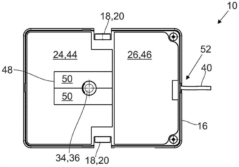
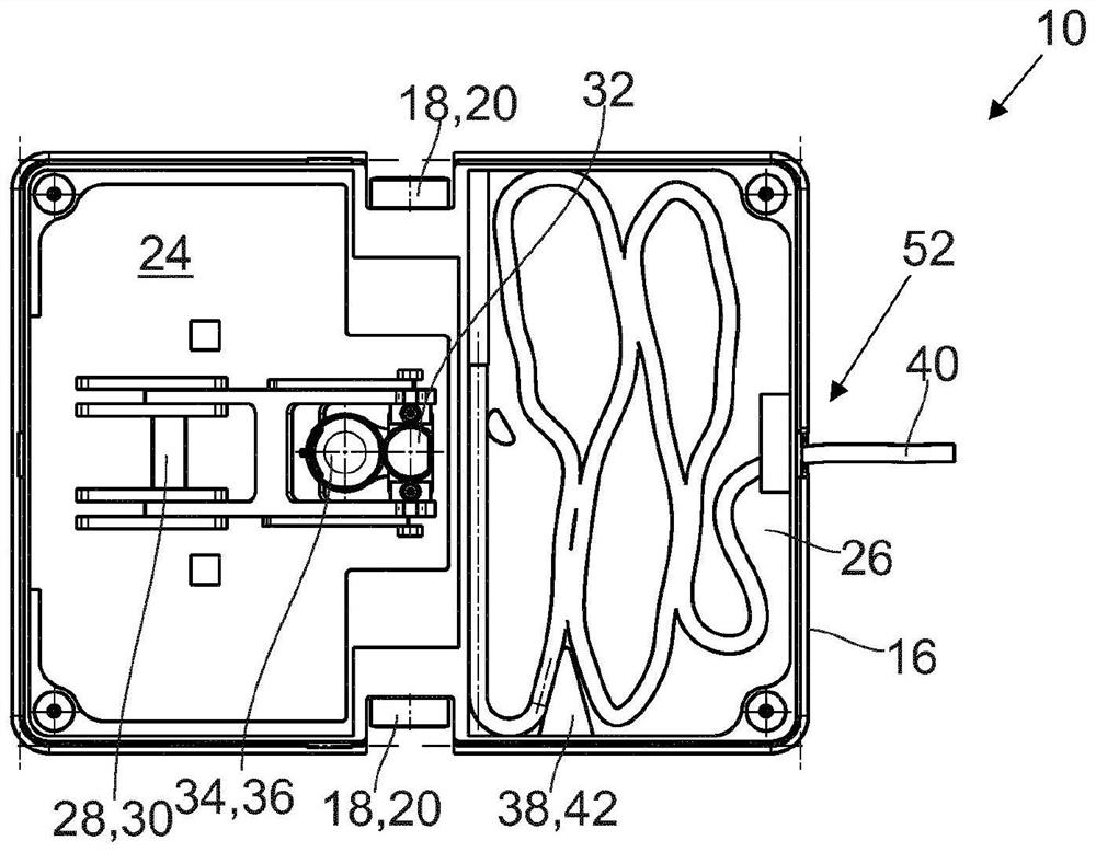
[0061] exist Figure 1A to Figure 1C Various views of an embodiment of a charging robot 10 according to the invention are shown in , so the following explanation refers to these three figures. Described charging robot 10 is used for vehicle 14 (see Figure 6) to charge the electrical energy storage 12, which will be discussed in more detail later. The charging robot 10 has a support structure 16 to which are attached rotatably about a common axis of rotation two wheels 18 which can be driven by a drive unit also attached to the support structure 16. 20 drives. The drive unit 20 may comprise two in-wheel motors by means of which the wheels 18 can be driven independently of each other. In addition to these two wheels, four auxiliary wheels 22 ( Figure 1C ) is attached to said support structure 16 and is rotatable about an axis of rotation (not shown) extending substantially vertically when used as intended. However, the auxiliary wheels 22 themselves are not driven and ens...


PUM


Abstract

The invention relates to a charging robot (10) for charging an electrical energy store (12) of a vehicle (14), comprising: a support structure (16); at least one wheel rotatably attached to the support structure (16); a drive unit (20) attached to the support structure (16) and capable of driving a wheel; a first containing space (24) and a second containing space (26), the first containing space is attached to or formed by the supporting structure (16), the second containing space is attached to or formed by the supporting structure (16), and the first containing space (24) and the second containing space (26) are arranged side by side; a lifting device (28) arranged in the first accommodation space (24), to which lifting device (28) a contact portion (32) is attached, which contact portion can be connected in an electrically transmissive manner to a mating contact portion (60) of the vehicle (14); and a charging cable (40) which is electrically conductively connected to the contact portion (32), by means of which electrical energy can be transmitted to the contact portion (32), the charging cable (40) extending through the second receiving space (26); and a guiding device (38) for guiding the charging cable (40) into the second accommodating space (26). The device also relates to a charging device (64) for charging an electrical energy store (12) of a vehicle (14), and to a vehicle (14) with which an electrical energy store of a vehicle can be charged.

Description

technical field [0001] The invention relates to a charging robot and a charging device for charging an electrical energy store of a vehicle. Furthermore, the device relates to a vehicle whose electrical energy store can be charged with such a charging device. Background technique [0002] In an effort to reduce CO 2 In the process of emissions, increasing the electrification of vehicles comes into focus. While vehicles powered by alternative fuels such as fossil fuels or hydrogen can be refueled relatively easily and in a relatively short period of time, charging the electrical energy storage of an electric vehicle is a more complex and lengthy process. To charge the electrical energy store, the plug connected to the charging station via a charging cable is usually connected to a correspondingly designed socket of the vehicle concerned. After the charging process is complete, the plug can be pulled out of the socket and the vehicle can be moved again. The charging statio...

Claims


Application Information

Patent Timeline
Patent Type & Authority Applications(China)
IPC IPC(8): B60L53/14B60L53/35B60L53/37B65H75/36B66D1/36B66F7/06H02G11/00
CPCB60L53/14B60L53/35B60L53/37B66D1/36H02G11/003B65H75/368B65H2701/34B66F7/0691Y02T10/70Y02T10/7072Y02T90/12B60L53/18B25J11/008B25J5/007B25J19/022B60Y2200/91Y02T90/14B60L53/16
Inventor W·沃夫舒尔特M·韦施勒J·费克勒U·鲍迈斯特D·雷尔R·泰奇曼M·米特巴赫B·内格尔G·福斯
Owner IMS GEAR SE & CO KGAA
Learn More