Novel feeding assembly of full-automatic anaerobic glue injection machine

A glue injection machine, fully automatic technology, applied to the device and coating of the surface coating liquid, can solve problems such as unfavorable automation of production, adjustment of materials that cannot be reclaimed, etc., to improve automation, ensure speed, The effect of wide applicability

Active Publication Date: 2022-04-05
瑞安市杰峰智能科技有限公司
View PDF13 Cites 0 Cited by
  • Summary
  • Abstract
  • Description
  • Claims
  • Application Information

AI Technical Summary

Problems solved by technology

[0003] The main part of the filter includes the end cover. As the main part of the filter, it needs to be injected with glue during the processing process for connection. Generally, glue is injected on the glue injection machine for automation, but currently The feeding process of the glue machine generally requires manual participation. Putting the end caps on the feeding port in an orderly manner requires a lot of time for personnel to participate, which is not conducive to automated production, and it is also impossible to adjust the feeding according to the size of the material.

Method used


Image

  • Novel feeding assembly of full-automatic anaerobic glue injection machine
  • Novel feeding assembly of full-automatic anaerobic glue injection machine
  • Novel feeding assembly of full-automatic anaerobic glue injection machine

Examples


Embodiment

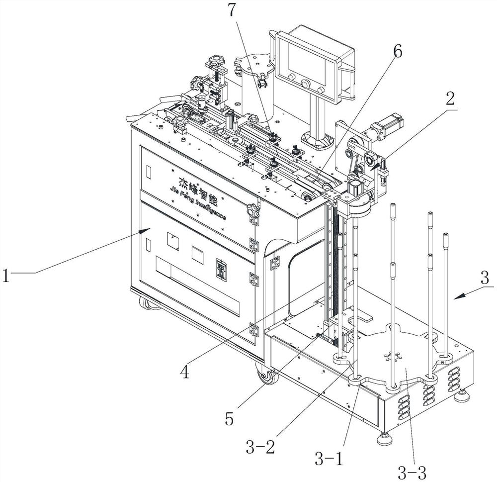
[0029] Such as Figure 1 to Figure 3 As shown, the present invention discloses a new type of feeding assembly of a fully automatic anaerobic glue injection machine. In view of the current filter end cap feeding, the staff needs to take the end caps to the feeding area and place them one by one. Regarding the problem of conveyor belt 7, this scheme changes the feeding area to automatic feeding through reasonable design, which can greatly increase the processing efficiency and reduce the participation of personnel. The specific scheme design is as follows:

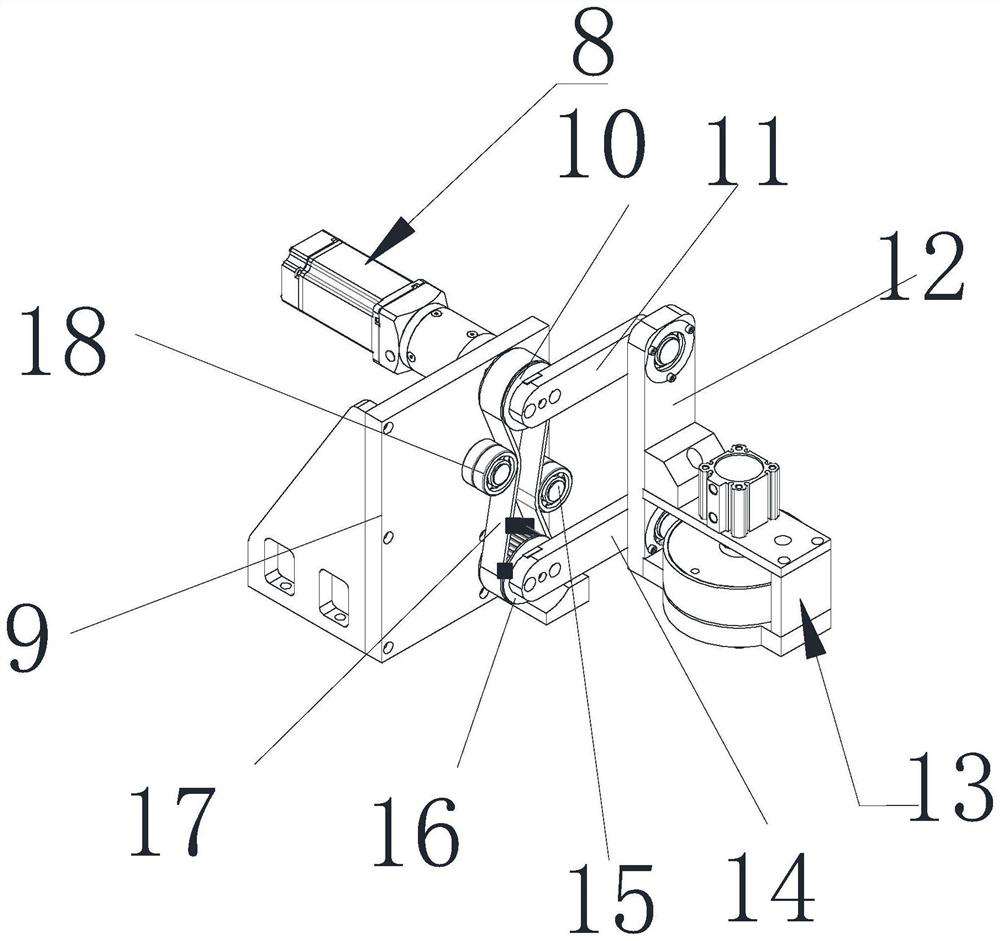
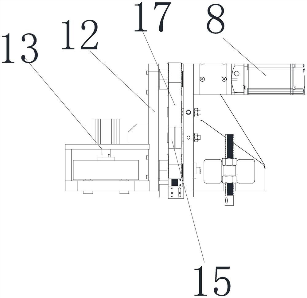
[0030] The feeding mechanism of the automatic anaerobic glue injection machine includes the glue injection machine body 1, the glue injection machine body 1 includes the feeding component 3, the feeding area 6 and the feeding unit 2, the feeding unit 2 includes the installation Seat 9, driver 8, swing rod 11 and self-adjusting grabbing mechanism, mounting seat 9 is installed on the feeding area 6, specifically side, the driv...


PUM


Abstract

The invention relates to a novel feeding assembly of a full-automatic anaerobic glue injection machine, which is characterized by comprising a glue injection machine body, the glue injection machine body comprises a feeding assembly, a feeding area and a feeding unit, the feeding unit comprises a mounting seat, a driver, a swing rod and a self-adjusting grabbing mechanism, the mounting seat is mounted on the feeding area, the driver is mounted on the mounting seat, and the swing rod is mounted on the self-adjusting grabbing mechanism. The driver is installed on the back side of the installation seat, the driving synchronizing wheel is installed on the front side of the installation seat, the driving synchronizing wheel is connected with the output end of the driver and is controlled by the driver to rotate, the swing arm is installed at the end of the driving synchronizing wheel, a protruding shaft is arranged on the other side of the swing arm, and the protruding shaft is connected with the driving synchronizing wheel. The self-adjusting grabbing mechanism comprises a connecting plate and a grabbing unit installed on the connecting plate, a through hole is formed in the upper end of the connecting plate, an upper bearing is installed in the through hole, a protruding shaft of the swing arm and the bearing of the connecting plate are installed in a matched mode, the driver works, the driving synchronizing wheel rotates to drive the swing arm to swing, and then the grabbing unit swings. According to the feeding machine applied to the full-automatic anaerobic glue injection machine, the self-adjusting grabbing mechanism is adopted, materials can be automatically grabbed, manual participation is not needed, the feeding speed is guaranteed, automation is improved, the usability is wide, and the feeding machine can adapt to grabbing of different materials.

Description

technical field [0001] The invention relates to the technical field of filter processing, in particular to a novel feeding assembly for a fully automatic anaerobic glue injection machine. Background technique [0002] A filter refers to an accessory that filters impurities or gases through filter paper. Generally refers to the car filter, which is an accessory of the engine. [0003] The main part of the filter includes the end cover. As the main part of the filter, it needs to be injected with glue during the processing process for connection. Generally, glue is injected on the glue injection machine for automation, but currently The feeding process of the melter generally requires manual participation. Putting the end caps on the feeding port in an orderly manner requires a lot of time for personnel to participate, which is not conducive to automated production, and cannot be adjusted according to the size of the material. [0004] In view of the above problems, the pres...

Claims


Application Information

Patent Timeline
Patent Type & Authority Applications(China)
IPC IPC(8): B05C13/02B05C5/02
CPCY02E60/10
Inventor 胡立杰胡艳朝胡尹君李林
Owner 瑞安市杰峰智能科技有限公司
Why Eureka
Try Eureka