
Automatic carrying and blanking mechanism and method for narrow-edge parts

A conveying mechanism and narrow edge technology, applied in the field of machinery, can solve the problems of production line interruption, inconvenient clamping, workpiece damage, etc., and achieve the effects of convenient replacement and adjustment, reducing impact force and reducing noise.

Pending Publication Date: 2022-04-05
NANJING KANGNI PRECISION MECHANICS
View PDF0 Cites 0 Cited by
  • Summary
  • Abstract
  • Description
  • Claims
  • Application Information

AI Technical Summary

Problems solved by technology

In multi-station continuous processing, the workpiece is transported by the manipulator, because the narrow side parts protrude less from the mold, and it is not convenient for the jaws of the manipulator to clamp
The workpiece needs to be placed on the mold base station before punching, and the workpiece needs to be taken out after punching. During the process of picking and discharging, it is dangerous for the jaws of the manipulator to only hold the narrow side of the workpiece, and it is easy to fall off, causing damage to the workpiece. Damage and interruption of the production line

Method used


Image

  • Automatic carrying and blanking mechanism and method for narrow-edge parts
  • Automatic carrying and blanking mechanism and method for narrow-edge parts
  • Automatic carrying and blanking mechanism and method for narrow-edge parts

Examples


Embodiment Construction

[0036] The present invention is described in further detail now in conjunction with accompanying drawing. These drawings are all simplified schematic diagrams, which only illustrate the basic structure of the present invention in a schematic manner, so they only show the configurations related to the present invention.

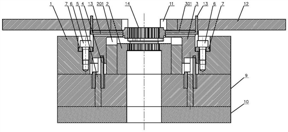
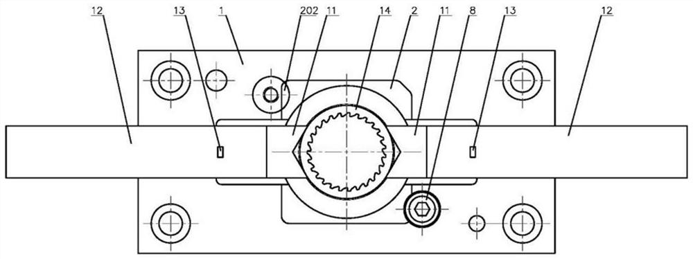
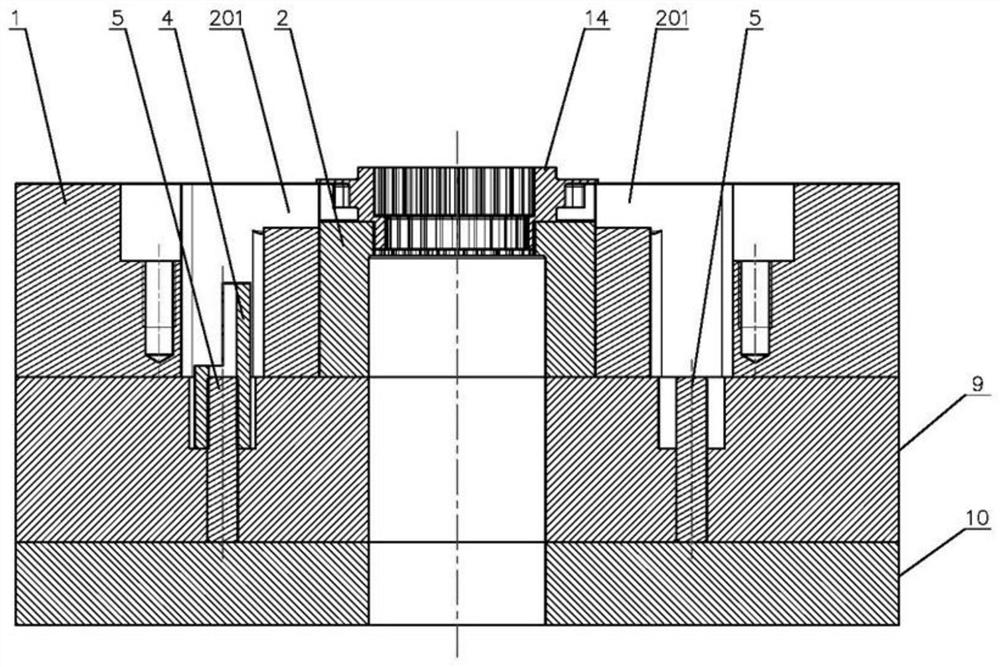
[0037] Such as Figure 1 to Figure 6 As shown, the automatic handling and blanking mechanism of the narrow edge parts of the present invention includes a support pad 9, the support pad 9 is fixed above the drop pad 10, and a fixed die 1 is fixed above the support pad 9, and the fixed concave die 1 is fixed above the support pad 9. A punching die 2 is embedded in the central square hole of the die 1, and the workpiece 14 is placed above the punching die 2 and the lower waste of the workpiece 14 is positioned in the die hole of the punching die 2. There is a clamping and conveying mechanism, and the below of the clamping and conveying mechanism is provided with...


PUM


Abstract

The invention relates to an automatic carrying and blanking mechanism and method for narrow-edge parts, and the mechanism is characterized in that a fixed female die is fixed above a supporting cushion block, a punching female die is embedded in a central square hole of the fixed female die, a workpiece is placed above the punching female die, and lower waste materials of the workpiece are located in a die hole of the punching female die; clamping and carrying mechanisms are arranged on the two sides of the workpieces, and floating mechanisms used for lifting the workpieces are arranged below the clamping and carrying mechanisms. The floating mechanism comprises a pair of floating blocks, the vertical parts of the floating blocks are perpendicularly inserted into vertical guide grooves of the fixed female die, the horizontal parts of the floating blocks extend in the direction of the workpiece, the ends of the floating blocks are inserted into female die caulking grooves in the top of the punching female die, and floating block tooth grooves in the opposite ends of the two floating blocks are clamped to outer teeth on the two sides of the workpiece respectively and matched with the outer teeth. An elastic assembly is arranged at the bottom of the floating block. The method is based on the mechanism, and discharging, blanking and transferring of all workpieces are sequentially and circularly completed. According to the automatic feeding device, workpieces can be floated, feeding and taking are conducted, and clamping is reliable.

Description

technical field [0001] The invention relates to an automatic conveying and punching mechanism and method for narrow side parts, belonging to the technical field of machinery. Background technique [0002] There is a piece of waste in the lower part of the workpiece with a toothed inner hole, which needs to be cut off. The specific shape of the narrow side parts applicable to the present invention is that the upper circumference of the workpiece is provided with a flange, and the outer teeth for positioning are arranged under the flange, the bottom end surface of the effective section of the workpiece is used as a supporting surface, and the waste protrudes from the edge of the effective section of the workpiece. The lower part and the outer diameter is smaller than the internal tooth hole of the workpiece. The upper part of the waste forms an inner step at the lower part of the inner tooth hole of the workpiece, and the part below the inner step needs to be punched out with...

Claims


Application Information

Patent Timeline
Patent Type & Authority Applications(China)
IPC IPC(8): B21D28/14B21D28/02
CPCY02P70/10
Inventor 袁天宇吴昊孙炜查光成李振红蒋哲东
Owner NANJING KANGNI PRECISION MECHANICS
Learn More