Flexible stirrup continuous feeding positioning machine and feeding positioning method

A positioning mechanism and stirrup technology, applied in auxiliary devices, applications, auxiliary welding equipment, etc., can solve the problems of inconvenient automatic production of stirrup cages, etc., and achieve the effect of simple structure, easy adjustment, and easy control

Pending Publication Date: 2022-04-05
RBS PARTNERS S&T CO LTD
View PDF0 Cites 0 Cited by
  • Summary
  • Abstract
  • Description
  • Claims
  • Application Information

AI Technical Summary

Problems solved by technology

First of all, on the automated production line, grid stirrups have two continuous positioning requirements before welding: one is the pre-positioning of the transferred stirrup group; the other is welding positioning during welding; currently there is no corresponding grid in the market Mesh stirrup continuously meets the two positioning requirements of the mechanism
Secondly, the grid stirrups in the existing building codes are single-stirrup bending process, which is not convenient for the automatic production of stirrup cages; thirdly, there is no automatic continuous positioning equipment corresponding to this kind of grid stirrups in the market

Method used


Image

  • Flexible stirrup continuous feeding positioning machine and feeding positioning method
  • Flexible stirrup continuous feeding positioning machine and feeding positioning method
  • Flexible stirrup continuous feeding positioning machine and feeding positioning method

Examples


Embodiment 1

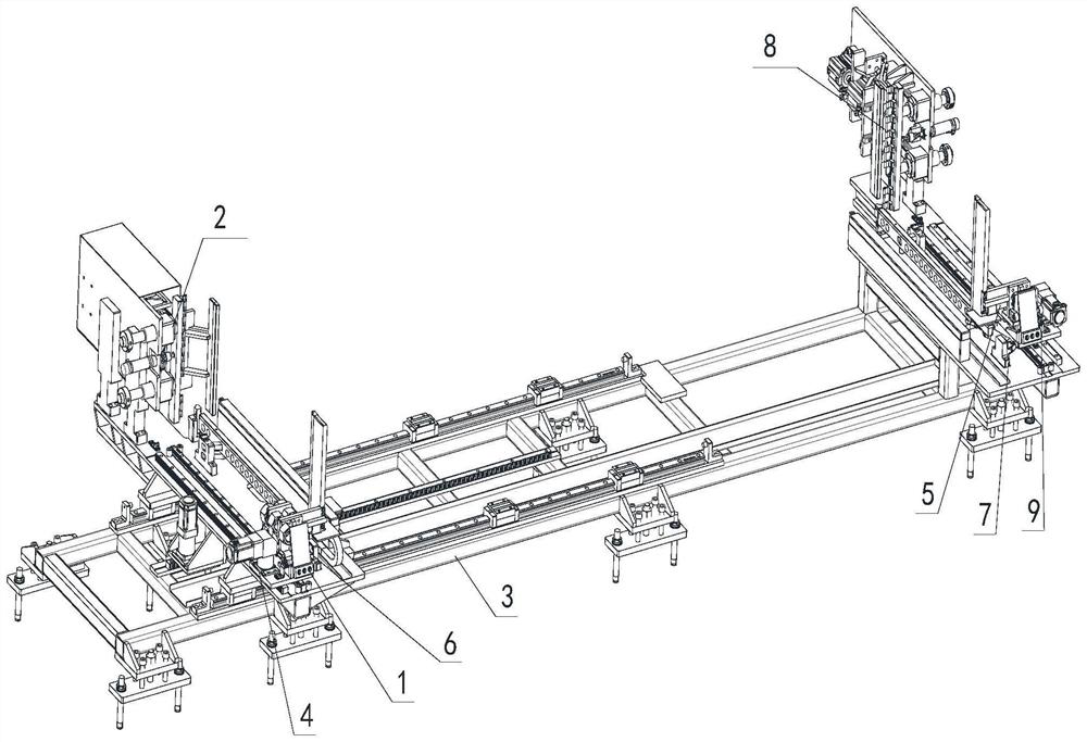
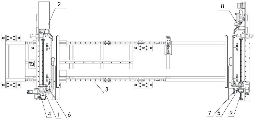
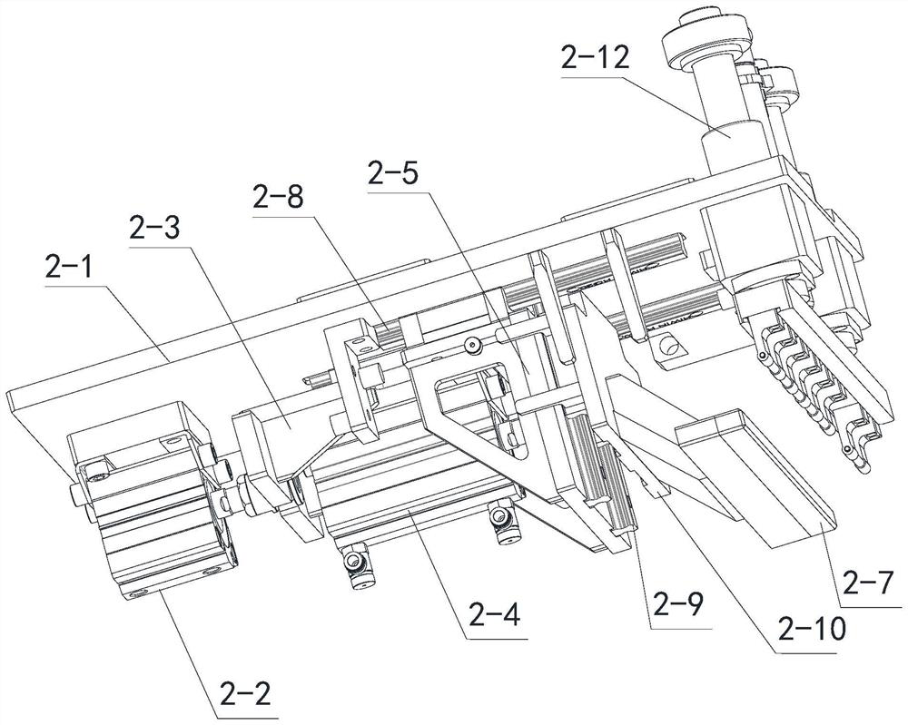
[0036] See Figure 1 to Figure 8 , the flexible stirrup continuous feeding positioning machine of the present embodiment includes a control cabinet, an underframe, a left chain plate support mechanism and a right chain plate support mechanism arranged on the underframe, and the left chain plate support mechanism is provided with a The left alignment mechanism, the left pushing mechanism and the left positioning mechanism electrically connected to the control cabinet, the right chain plate supporting mechanism is provided with the right alignment mechanism, the right pushing mechanism and the right positioning mechanism electrically connected to the control cabinet, the The left alignment mechanism and the right alignment mechanism are used to align the stirrups left and right, the left pushing mechanism and the right pushing mechanism are used to push the stirrups, and the left positioning mechanism and the right positioning mechanism are used for Dual position front and rear ...


PUM


Abstract

The flexible stirrup continuous feeding and positioning machine comprises a control cabinet, a bottom frame, a left chain plate supporting mechanism and a right chain plate supporting mechanism, the left chain plate supporting mechanism and the right chain plate supporting mechanism are arranged on the bottom frame, and the left chain plate supporting mechanism is provided with a left alignment mechanism, a left pushing mechanism and a left positioning mechanism which are electrically connected with the control cabinet; the right chain plate supporting mechanism is provided with a right alignment mechanism, a right pushing mechanism and a right positioning mechanism which are electrically connected with the control cabinet, the left alignment mechanism and the right alignment mechanism are used for conducting left-right alignment on the stirrups, and the left pushing mechanism and the right pushing mechanism are used for pushing the stirrups. The left positioning mechanism and the right positioning mechanism are used for conducting double-position front-back positioning on the stirrup. The invention further provides a feeding positioning method of the flexible stirrup continuous feeding positioning machine. The stirrup automatic welding device solves the technical problems of automatic clamping, automatic feeding and automatic positioning of stirrups during automatic welding of the stirrup cage, and automatic production of the stirrup cage is facilitated. And the flexible requirements of length, height and diameter changes of the stirrup are met.

Description

technical field [0001] The invention relates to the technical field of reinforcement cage welding equipment, in particular to a flexible stirrup continuous feeding positioning machine and a feeding positioning method. Background technique [0002] In the field of construction engineering, steel bars are widely used. When building a house, it is necessary to build steel bars into the form of steel cages and then grout them to form walls and other buildings. At present, there is a great demand for steel cage products in the market, and the forming is basically done manually, with low work efficiency and high labor intensity, so an automatic equipment for steel cages is needed to solve these problems. In order to meet the needs of automation (stirrup standardization, digitization, simplification of the difficulty of automation, etc.), a welded grid stirrup was produced (see attached figure 1 ), using the information of the four corners of the grid stirrup to realize the automa...

Claims


Application Information

Patent Timeline
Patent Type & Authority Applications(China)
IPC IPC(8): B23K37/00B23K37/047B21F27/20
Inventor 刘付钧刘紫敬李祖保黎岭江青华曾知超方洪飞
Owner RBS PARTNERS S&T CO LTD
Why Eureka
Try Eureka