Tank container

A tank container and tank body technology, which is applied in the field of tank container manufacturing, can solve problems such as low production efficiency and long painting hours, and achieve the effects of improving production efficiency, reducing labor intensity, and reducing workload

Pending Publication Date: 2022-04-05
NANTONG CIMC TANK EQUIP CO LTD
0 Cites 0 Cited by

AI-Extracted Technical Summary

Problems solved by technology

[0005] The purpose of the present invention is to provide a tank container to solve the problems of long...

Method used

In the present embodiment, the front end frame 2 can be welded in advance to be provided with a protruding connection ring 31, and the connection ring 31 is connected with the tank body 1 at intervals, so as to avoid direct welding from destroying the connection ring 31 on the front end frame 2. The paint layer realizes the separate painting manufacture of the front frame 2.
Please refer to Fig. 1, Fig. 1 has shown the specific structure of a kind of tank container provided by the present embodiment, it mainly comprises tank body 1 and the front end frame 2 and rear end frame 3 that are relatively arranged at tank body 1 two ends . Wherein, the rear end of the tank body 1 is provided with a protruding first reinforcing member 11 to be correspondingly connected to the second reinforcing member 32 protruding from the rear end frame 3, so as to realize the connection between the tank body 1 and the rear end frame 3. The non-welded connection is fixed, so as to realize the step-by-step manufacturing of the tank container, and the large components such as the end frame can be manufactured in advance and prefabricated with paint, without spraying the whole container, which shortens the manufacturing time of the tank container.
Please refer to Fig. 3, tank body 1 is also provided with two backing plates 12, two first reinforcing ribs 13 and two second reinforcing ribs 14 that are arranged correspondingly with transition piece 15, to further improve the intensity of structure .
Therefore, the tank body 1, the front end frame 2, the rear end frame 3, and the bottom side beam assembly 5 can be manufactured separately, and painted respectively according to the anti-corrosion requirements, so as to reduce the requirements of the paint room and realize step-by-step manufacturing.
[0035] In order to solve the above technical problems, the present embodiment provides a tank container, which includes a tank body and a front frame and a rear frame relatively arranged at both ends of the tank body, and additionally set between the tank body and the rear frame Two reinforcements to ensure the strength of the connection. Among them, the first reinforcement is attached to the tank body, and the second reinforcement is attached to the rear end frame. Through the connection between the two reinforcements, direct welding is avoided to damage the paint layer of the ...

Abstract

The invention provides a tank container which comprises a tank body, a front end frame and a rear end frame, the front end frame and the rear end frame are oppositely arranged at the two ends of the tank body, the tank body comprises a tank body and two first reinforcing pieces arranged at the rear end of the tank body, the two first reinforcing pieces are oppositely spaced, one end of each first reinforcing piece is fixed to the lower portion of the tank body, and the other end of each first reinforcing piece is suspended; the rear end frame comprises a frame body, a connecting ring and two second reinforcing pieces; a concave part is concavely arranged at the bottom of the frame body; the connecting ring and the second reinforcing piece protrude from the frame body to the tank body, and a notch is formed in the bottom of the connecting ring and is opposite to the concave part; the two second reinforcing pieces are arranged on the two sides of the notch respectively; the connecting ring is connected with the rear end of the tank body, and the two second reinforcing pieces are correspondingly connected with the suspended ends of the two first reinforcing pieces respectively. According to the tank container, the tank body and the end frame can be separately manufactured and painted, the whole container does not need to be painted, and the production efficiency of the tank container is improved.

Application Domain

Large containers

Technology Topic

Structural engineeringIndustrial engineering +1

Image

  • Tank container
  • Tank container
  • Tank container

Examples

  • Experimental program(1)

Example Embodiment

[0033] Typical embodiments that embody the features and advantages of the present invention will be described in detail in the following description. It should be understood that the present invention is capable of various changes in different embodiments without departing from the scope of the present invention, and that the description and illustrations therein are illustrative in nature and not limiting. this invention.
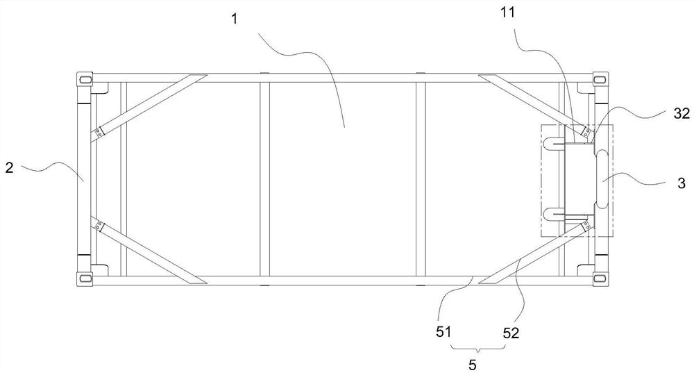
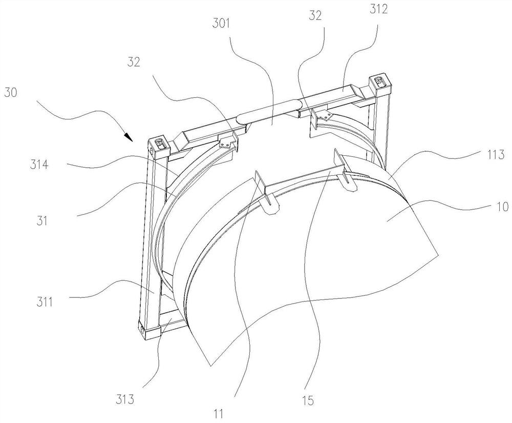
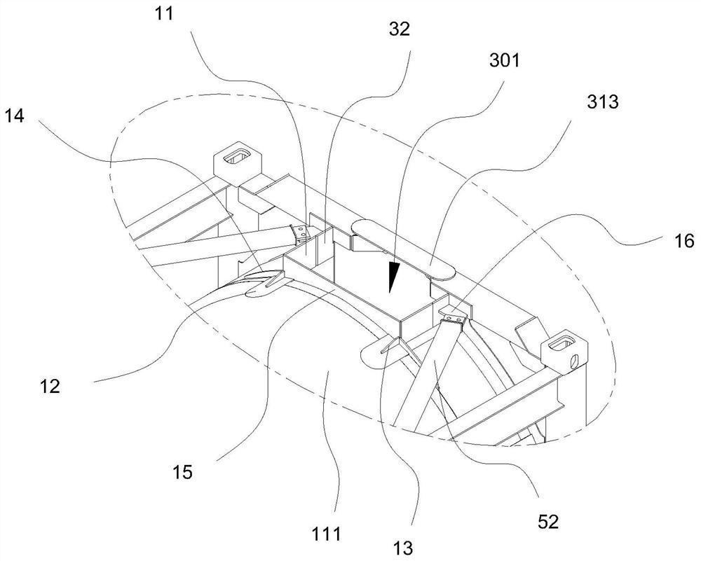
[0034] In the related art, the bottom of the rear end of the tank body has a discharge port, and a bottom valve is arranged at the discharge port. In order to provide enough operating space at the discharge port, the bottom beam of the rear end frame of the tank body near the discharge port needs to be broken into two sections, and connected by a bottom plate to form a U-shaped gap, which can prevent The bottom valve interferes with the end lower beam. Due to the existence of the gap, it is necessary to set a rear bottom reinforcement component on the rear frame correspondingly, so as to ensure the strength of the frame. The bottom reinforcement component at the rear end is usually connected between the end frame and the tank body by integral welding, and then painted as a whole.
[0035] In order to solve the above technical problems, this embodiment provides a tank container, which includes a tank body and a front frame and a rear frame oppositely arranged at both ends of the tank body, and two reinforcements are respectively added between the tank body and the rear frame. parts to ensure the strength of the connection. Among them, the first reinforcement is attached to the tank body, and the second reinforcement is attached to the rear end frame. Through the connection between the two reinforcements, direct welding is avoided to damage the paint layer of the end frame, so that the tank body and the end frame are fully integrated. manufactured separately. The rear end frame can be pre-painted during manufacture, and then assembled to form a complete tank container. There is no need to paint the entire container, which reduces the workload of painting, and also eliminates the overall handling of the tank during the painting process, improving the tank container. container production efficiency.
[0036] Please refer to figure 1 , figure 1 The specific structure of a tank container provided in this embodiment is shown, which mainly includes a tank body 1 and a front end frame 2 and a rear end frame 3 arranged oppositely at both ends of the tank body 1 . Wherein, the rear end of the tank body 1 is provided with a protruding first reinforcing member 11 to be correspondingly connected to the second reinforcing member 32 protruding from the rear end frame 3, so as to realize the connection between the tank body 1 and the rear end frame 3. The non-welded connection is fixed, so as to realize the step-by-step manufacturing of the tank container, and the large components such as the end frame can be manufactured in advance and prefabricated with paint, without spraying the whole container, which shortens the manufacturing time of the tank container.
[0037] Please refer to figure 1 , the tank 1 includes a tank body 10 and two first reinforcements 11 disposed at the rear end of the tank body 10 .
[0038] The tank body 10 is a pressure vessel made of stainless steel, used for storing liquid food or chemicals, and has better anti-corrosion performance and sufficient strength to withstand higher liquid pressure.
[0039] Please combine figure 2The tank body 10 includes a cylinder body 111 and a front head (not shown) and a rear head 113 respectively sealed at the front and rear ends of the cylinder body 111 . Wherein, the bottom of the rear head 113 has a discharge port for material discharge.
[0040] The two first reinforcements 11 are arranged on the bottom of the tank body 10 at intervals opposite to each other, and protrude out along the axial direction of the tank body 1 near the rear head 113 . One end of each first reinforcing member 11 is welded and fixed to the outer wall of the tank body 10 , and the other end is suspended in the air for connecting to the second reinforcing member 32 .
[0041] The first reinforcing member 11 is also made of the same stainless steel material as the tank body 10 , based on the anti-corrosion requirement that it is directly connected with the tank body 10 .
[0042] In this embodiment, the two first reinforcing pieces 11 are connected by a transition piece 15 .
[0043] The transition piece 15 is a strip-shaped structure, and one side of the transition piece 15 has an arc-shaped profile adapted to the outer circumference of the tank body 10, so as to stand upright on the outer wall of the tank body 10, and the other side for straight sides. Two ends of the transition piece 15 along the length direction are respectively bent and extended to the same side to extend out of the first reinforcing piece 11 .
[0044] The first reinforcing piece 11 is in the shape of a flat plate, perpendicular to the transition piece 15 and protruding toward the end frame.
[0045] Preferably, the two first reinforcing pieces 11 are integrally bent and formed by the transition piece 15, and the integral structure can effectively improve the strength of the overall structure. In other embodiments, the two first reinforcing pieces 11 and the transition piece 15 can be independent parts, which are integrated by welding.
[0046] Please refer to image 3 The tank body 1 is further provided with two backing plates 12, two first reinforcement ribs 13 and two second reinforcement ribs 14 corresponding to the transition piece 15, so as to further improve the strength of the structure.
[0047] Wherein, the two backing plates 12 are attached to the bottom of the tank body 10 and are spaced apart from each other, so that the two ends of the transition piece 15 (the first reinforcing piece 11 ) are erected on the two backing plates 12 respectively.
[0048] The backing plate 12 extends along the axial direction of the tank body 1 and is attached to the joint between the cylinder body 111 and the rear head 113 . The front end of the backing plate 12 is arc-shaped, which is not easy to flang and be damaged; the back end of the backing plate 12 is a straight edge, which abuts against the end of the transition piece 15 and is fixed by welding.
[0049] The two first reinforcing ribs 13 are erected on the bottom of the tank body 10 and are respectively connected and fixed to the two ends of the transition piece 15 .
[0050] The first reinforcing rib 13 is an approximately triangular plate structure, extending along the axial direction of the tank body 1 , and erected on the backing plate 12 for connecting the reinforcing backing plate 12 and the transition piece 15 . The front end of the first reinforcing rib 13 does not exceed the front end surface of the backing plate 12 . The first reinforcing rib 13 is substantially flush with the first reinforcing member 11 .
[0051] Likewise, the two second reinforcing ribs 14 are erected on the bottom of the tank body 10 and respectively connected and fixed to the two first reinforcing members 11 correspondingly.
[0052] The second reinforcing rib 14 is a strip-shaped flat plate structure extending along the circumference of the tank body 10 and has an arc-shaped profile adapted to the outer peripheral wall of the tank body 1 so as to stand upright on the outer peripheral wall. The second reinforcing rib 14 is vertically connected to the backing plate 12 and the first reinforcing member 11 .
[0053] Please refer back to figure 2 , the rear end frame 3 includes a frame body 30 , a connecting ring 31 and two second reinforcing pieces 32 . Wherein, a lower end of the frame body 30 is recessed with a recessed portion 301 . Both the connecting ring 31 and the second reinforcing member 32 protrude from the frame body 30 toward the tank body 1, and the lower end of the connecting ring 31 has a notch, which is opposite to the recessed portion 301; the two second reinforcing members 32 are respectively arranged on On both sides of the gap; the connecting ring 31 is connected to the rear end of the tank body 10 , and the two second reinforcements 32 are connected to the suspended ends of the two first reinforcements 11 respectively.
[0054] Specifically, the frame body 30 includes two relatively spaced uprights 311, upper end beams 312 and lower end beams 313 respectively connected to the upper and lower ends of the two uprights 311, and connections between the upright columns 311 and the upper end beams 312/lower end beams 313. Multiple diagonal braces 314 between.
[0055] Wherein, the middle part of the end lower beam 313 is depressed to form an approximately V-shaped concave portion 301 , and the concave portion 301 is arranged correspondingly to the bottom valve at the discharge port of the tank body 1 .
[0056] The bottom of the connecting ring 31 has a notch corresponding to the concave portion 301 .
[0057] The outer edge of one end of the connecting ring 31 is welded and fixed with two uprights 311 and the braces 314 respectively, and the other end exceeds the inner surface of the uprights 311 along the axial direction of the tank body 1 and is welded and fixed with the rear head 113 of the tank body 1 .
[0058] The two second reinforcing pieces 32 are respectively disposed on two ends of the gap of the connecting ring 31 .
[0059] Specifically, the second reinforcing member 32 is in the shape of a flat plate, located inside the notch, and connected to the connecting ring 31 and the frame body 30 respectively. The second reinforcing member 32 protrudes forward from the front end of the connecting ring 31 in the axial direction, so as to be correspondingly connected and fixed with the first reinforcing member 11 .
[0060] Please also refer to Figure 4 and Figure 5 , the first reinforcing member 11 and the second reinforcing member 32 are aligned for butt welding, so as to realize the reinforced connection between the tank body 1 and the rear end frame 3 .
[0061] Please refer to Image 6 , the first reinforcement 11 and the second reinforcement 32 are staggered for lap welding, so as to realize the reinforced connection between the tank body 1 and the rear end frame 3 .
[0062] Please refer to Figure 7 The first reinforcing member 11 and the second reinforcing member 32 are correspondingly provided with connecting holes, and the two are overlapped so that the respective connecting holes are opposite to each other, so as to be used for passing through suitable bolts and fasteners. The detachable bolt connection facilitates loading and unloading.
[0063] Please refer to Figure 8 The ends where the first reinforcement 11 and the second reinforcement 32 meet are bent, and the ends are correspondingly provided with connection holes. The two ends are fit together so that the respective connecting holes are opposite to each other, so that the matching flanges can pass through. The detachable flange connection facilitates assembly and disassembly.
[0064] In this embodiment, the frame body 30 of the rear end frame 3 is made of carbon steel, which has high strength and rigidity, but is relatively easy to rust, and requires appropriate anti-corrosion treatment, such as painting or galvanizing. The connecting ring 31 and the two second reinforcing members 32 are made of stainless steel, which has anti-corrosion properties. After the connecting ring 31 and the second reinforcing member 32 are respectively welded to the frame body 30, anti-corrosion paint spraying treatment needs to be done on the outer surface of the frame body 30, and the paint should also cover the frame body 30 and the second connecting member. The welds between the rings 31 and the welds between the frame body 30 and the second reinforcement 32 .
[0065] In this embodiment, the front frame 2 can be welded in advance to be provided with a protruding connecting ring 31, and the connecting ring 31 is connected to the tank body 1 at intervals, so as to avoid direct welding from damaging the paint layer on the front frame 2, Realize the separate painting manufacture of the front frame 2.
[0066] Please refer back to image 3 and Figure 4 , the tank container also includes four bottom side beam assemblies 5 respectively corresponding to the rear end frame 3 and the front end frame 2 , and the four bottom side beam assemblies 5 are symmetrically arranged on the bottom of the tank body 1 .
[0067] Each bottom side beam assembly 5 includes a bottom side beam 51 and a bottom brace 52 obliquely protruding from one side of the bottom side beam 51 toward the tank body 1 .
[0068] The bottom side beam 51 is located on one side of the tank body 1 and is arranged between two opposite bottom corners of the front end frame 2 and the rear end frame 3 .
[0069] The bottom brace 52 is welded on the inner side of the bottom side beam 51 and protrudes obliquely. An end of the bottom brace 52 away from the bottom side beam 51 is provided with a connecting hole for connecting to the lower end beam 313 of the rear end frame 3 .
[0070] The rear end frame 3 also includes two brace connectors 16 corresponding to the bottom braces 52 for further reinforcement.
[0071] The bracing connecting piece 16 is in the shape of a flat plate, and is interposed between the second reinforcing piece 32 and the frame body 30 . Specifically, the adjacent two side edges of the brace connector 16 are vertically connected to the surface of the second reinforcement member 32 beyond the connecting ring 31 and the inner surface of the frame body 30, and the protruding end of the brace connector 16 is inclined. A through hole corresponding to the connection hole is provided on the end. When one end of the bottom brace 52 overlaps the end of the brace connector 16 , the connecting hole is opposite to the through hole, so that the bolts can be detachably connected.
[0072] Please refer further Figure 9 The two ends of the bottom brace 52 are respectively provided with connecting holes, and the two corresponding brace connectors 16 are used to realize the bolt connection between the bottom side beam 51 and the front frame 2 (rear frame 3).
[0073] Based on the above, the first reinforcement 11 can be welded on the tank body 1 in advance; the second reinforcement 32 can be welded on the rear end frame 3 in advance. Moreover, the bottom brace 52 can be welded on the bottom side beam 51 in advance, and through the detachable connection with the brace connector 16 , the connection and fixation between the bottom side beam 51 and the rear end frame 3 can be realized. The brace connector 16 can be welded on the frame body 30 in advance, and paint needs to be sprayed on the connection between the two.
[0074] Therefore, the tank body 1, the front frame 2, the rear frame 3, and the bottom side beam assembly 5 can be manufactured separately, and painted separately according to the anti-corrosion requirements, reducing the requirements of the paint room and realizing step-by-step manufacturing.
[0075] The tank container provided in this embodiment not only ensures the strength of the rear end frame 3 through the connection between the first reinforcement 11 and the second reinforcement 32, but also avoids damage to the paint layer of the end frame by direct welding, thereby realizing The tank body 1 and the rear end frame 3 are manufactured separately, the rear end frame 3 can be painted in advance during manufacture, and then assembled to form a complete tank container, which eliminates the need for overall painting of the assembled tank container and reduces the need for painting The workload is reduced, the labor intensity is reduced, the production man-hour is shortened, and the production efficiency of tank container products is improved. And because of the reduction of spray paint, it can reduce the environmental pollution caused by volatile substances in the paint, meet the increasingly stringent environmental protection requirements, and have wide adaptability.
[0076] While this invention has been described with reference to several exemplary embodiments, it is understood that the terms which have been used are words of description and illustration, rather than of limitation. Since the present invention can be embodied in many forms without departing from the spirit or essence of the invention, it should be understood that the above-described embodiments are not limited to any of the foregoing details, but should be construed broadly within the spirit and scope of the appended claims. , all changes and modifications falling within the scope of the claims or their equivalents shall be covered by the appended claims.

PUM

no PUM

Description & Claims & Application Information

We can also present the details of the Description, Claims and Application information to help users get a comprehensive understanding of the technical details of the patent, such as background art, summary of invention, brief description of drawings, description of embodiments, and other original content. On the other hand, users can also determine the specific scope of protection of the technology through the list of claims; as well as understand the changes in the life cycle of the technology with the presentation of the patent timeline. Login to view more.

Similar technology patents

Installing method of portal crane

InactiveCN1833988ACable Wind Adjustment Reductionreduce workload
Owner:TONGJI UNIV

Automatic report generating method capable of meeting power distribution network management specific data standards

InactiveCN103714492Areduce workloadVersatile and practical
Owner:GUANGXI POWER GRID ELECTRIC POWER RES INST +1

Classification and recommendation of technical efficacy words

  • Reduce labor intensity
  • reduce workload

Method for intelligent automatic identification of transmission circuit parts

Owner:INFORMATION COMM COMPANY STATE GRID SHANDONG ELECTRIC POWER +2

City regional railway signal system and control method thereof

Owner:CHINA RAILWAY SIYUAN SURVEY & DESIGN GRP

Railway bearing intelligent on-line detection method and its device

InactiveCN101290265AReduce labor intensity
Owner:洛阳铭昊测控科技有限公司

Hospital gown

InactiveUS7181773B1reduce workloadquickly expose
Owner:WILLIAM BEAUMONT HOSPITAL

Performance Aware Peer-to-Peer Content-on-Demand

ActiveUS20090177792A1reduce workloadimproves perceive performance
Owner:THOMSON LICENSING SA

Method and apparatus for directionally grabbing page resource

InactiveCN101452463AIncrease yield and recallreduce workload
Owner:ZHEJIANG UNIV

Garbage classification prompt garbage can and system based on image recognition

InactiveCN107054936Areduce workloadachieve reuse
Owner:GUANGDONG MATVIEW INTELLIGENT SCI & TECH CO LTD

Construction site operation safety remote management and control system and method

InactiveCN107967562AReduce workloadSave human and material resources
Owner:TAIYUAN POWER SUPPLY COMPANY OF STATE GRID SHANXI ELECTRIC POWER +1
Why Eureka
Try Eureka