
A multi-way valve spool displacement detection device

A technology of valve core displacement and detection device, applied in valve device, valve operation/release device, multi-port valve, etc., can solve the problems of inability to change the direction of the oil, and can not carry out the direction of the oil, so as to achieve low cost. Effect

Active Publication Date: 2022-05-06
JIANGSU HENGLI HYDRAULIC TECH CO LTD
View PDF11 Cites 0 Cited by
  • Summary
  • Abstract
  • Description
  • Claims
  • Application Information

AI Technical Summary

Problems solved by technology

[0003] However, the existing multi-way valve spool displacement detection device, such as patent number: CN202020794623.1, patent name: a hydraulic valve spool displacement detection device, patent number: CN201320623319.0, patent name: hydraulic valve spool and displacement The connection structure of the detection device is directly measured by the displacement sensor, but it cannot be used for oil reversing; patent number: CN202110394050.2, patent name: a pilot valve for measuring the displacement of the multi-way valve spool, the application The pilot valve is used to detect the displacement of the spool; patent number: CN202111056497.5, patent name: device and method for real-time measurement of non-contact spool displacement based on spectral confocal, this application uses a special sensor to measure the displacement of the spool, but it cannot be changed through oil Towards

Method used


Image

  • A multi-way valve spool displacement detection device
  • A multi-way valve spool displacement detection device
  • A multi-way valve spool displacement detection device

Examples


Embodiment Construction

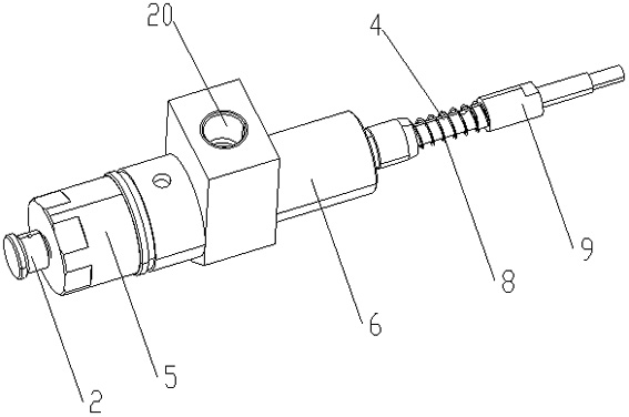
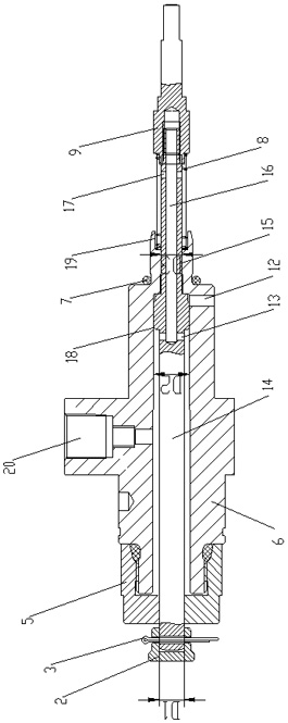
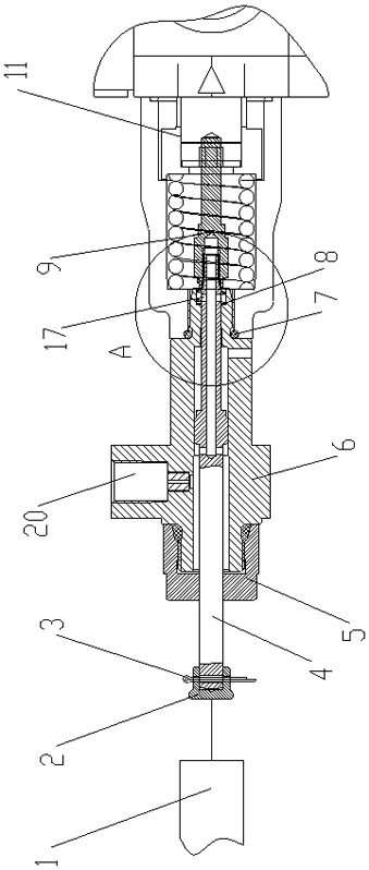
[0027] The present invention will now be described in further detail in conjunction with the accompanying drawings and preferred embodiments. These drawings are all simplified schematic diagrams, which only illustrate the basic structure of the present invention in a schematic manner, so they only show the configurations related to the present invention.

[0028] Such as Figure 1~6 A multi-way valve spool displacement detection device shown includes a tooling main body 6, a measuring piece and a displacement sensor 1. The displacement sensor 1 can be a common displacement sensor on the market, and one end of the tooling main body 6 is threaded to install the screw cap 5. , the displacement sensor 1 is set close to the screw cap 5, the other end of the tooling main body 6 is installed with the multi-way valve to be tested through threads, a seal 7 is installed between the tooling main body 6 and the end cap of the multi-way valve under test, and the tooling main body 6 is holl...


PUM


Abstract

The invention relates to the technical field of hydraulic auxiliary detection tooling, in particular to a multi-way valve spool displacement detection device. There is a measuring piece interspersed in the main body of the tooling. The measuring end of the measuring piece extends into the inner cavity of the multi-way valve to be tested and resists the spool of the multi-way valve under test. The core moves left and right in the main body of the tooling, the sensing end of the measuring piece protrudes from the screw cap, and is set facing the displacement sensor; there is a pilot oil port on the main body of the tooling, and the pilot oil port and the inner cavity of the main body of the tooling are set through. There is an oil passage, and it communicates with the inner cavity of the multi-way valve under test. The pilot oil port enters the oil, and sends it to the multi-way valve under test through the oil passage, so as to realize the oil flow through the measuring port. No special or special displacement sensor is needed, the displacement of the valve core can be directly measured through the common sensor on the market, without interfering with the normal operation of the measured valve; no replacement or special end cap is required; there is no gap between the entire measuring rod and the main body of the tooling The seal seals through the gap.

Description

technical field [0001] The invention relates to the technical field of hydraulic auxiliary detection tooling, in particular to a multi-way valve spool displacement detection device. Background technique [0002] Hydraulic transmission has the advantages of large power-to-mass ratio, easy speed adjustment and stable operation, and is widely used in construction machinery, walking machinery, aerospace and marine engineering and other fields. Hydraulic valves are the most commonly used hydraulic components in hydraulic systems, and their working stability directly affects the performance of the entire hydraulic system. The working state of the valve can be intuitively known from the displacement of the spool, so it is necessary to measure the real-time displacement of the spool. [0003] However, the existing multi-way valve spool displacement detection device, such as patent number: CN202020794623.1, patent name: a hydraulic valve spool displacement detection device, patent n...

Claims


Application Information

Patent Timeline
Patent Type & Authority Patents(China)
IPC IPC(8): F15B19/00F15B13/02F16K37/00F16K31/36F16K11/02
Inventor 汪立平郭言刘红光王斌
Owner JIANGSU HENGLI HYDRAULIC TECH CO LTD
Learn More