

Optical lighting device and optical modification equipment
A lighting device and optical technology, applied in the direction of optics, optical components, instruments, etc., can solve the problems of obvious queuing effect, difficulty in achieving uniformity, poor energy efficiency ratio, etc.
- Summary
- Abstract
- Description
- Claims
- Application Information
AI Technical Summary
Problems solved by technology
Method used
Image

Examples
Embodiment Construction
[0032] In order to enable those skilled in the art to better understand the solution of the present invention, the present invention will be further described in detail below in conjunction with the accompanying drawings and specific embodiments.
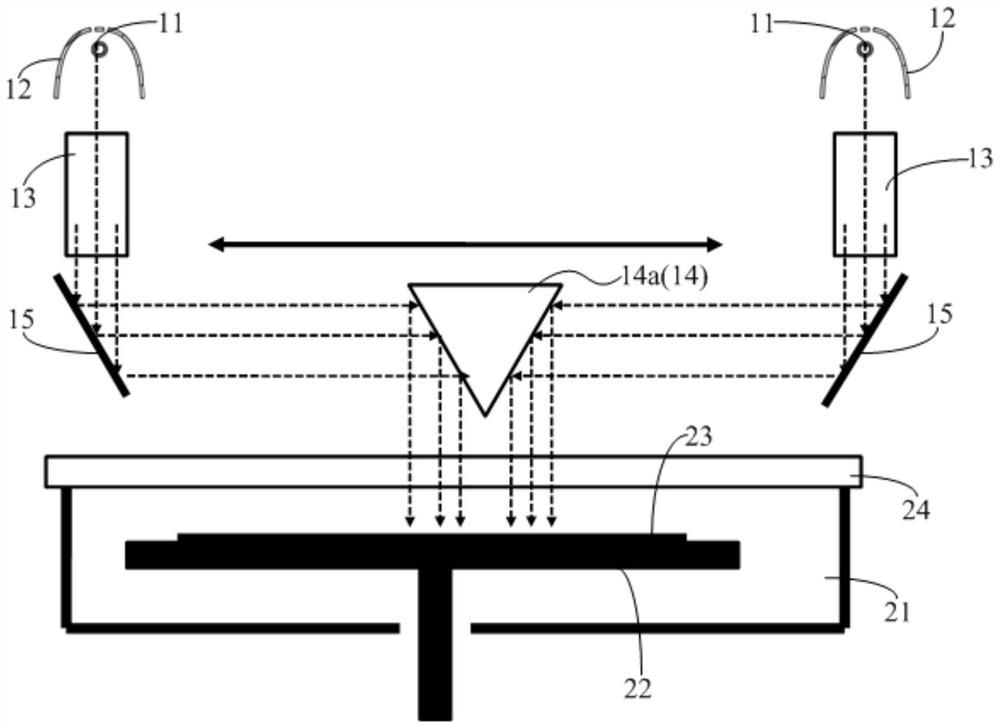
[0033] Without loss of generality, the specific structure of the optical lighting device is described below by taking the application of the optical lighting device to semiconductor wafer deposition thin film processing as an example. On this basis, the processed object of the optical lighting device is the wafer. In addition to the processing of semiconductor wafer thin films, the optical lighting device can also be applied to other fields with similar needs, such as optical modification of thin films in LED and flat panel display industries.
[0034] For ease of understanding and brevity of description, the following description will be combined with the optical lighting device and optical modification equipment, and the beneficial...
PUM
 Abstract
Description
Claims
Application Information