Automatic punching equipment and method for industrial production

A technology of punching equipment and air holes, applied in metal processing equipment, perforating tools, manufacturing tools, etc., can solve the problems of unable to cool the punch, easy to reduce the hardness of the punch, and wear of the punch, so as to achieve good protection and easy pick-and-place Convenience and high degree of automation

Pending Publication Date: 2022-04-08
江苏淮量智能科技有限公司
View PDF0 Cites 0 Cited by
  • Summary
  • Abstract
  • Description
  • Claims
  • Application Information

AI Technical Summary

Problems solved by technology

[0004] Aiming at the deficiencies of the prior art, the present invention provides an automatic punching equipment and method for industrial production, which solves the problem that the punching machine used in the punching process cannot usually cool the punch. During the continuous processing, the punch Heat can easily reduce the hardness of the punch, causing serious wear of the punch

Method used


Image

  • Automatic punching equipment and method for industrial production
  • Automatic punching equipment and method for industrial production
  • Automatic punching equipment and method for industrial production

Examples


Embodiment 1

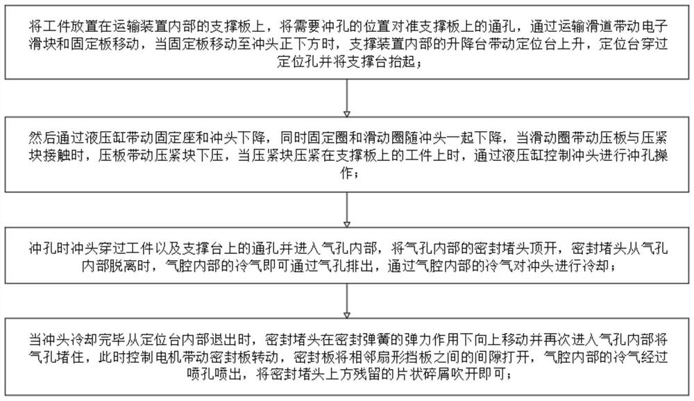
[0041] see Figure 2-4 , the present invention provides a technical solution: an automatic punching equipment for industrial production, specifically comprising:

[0042] A support frame 1, the inner wall of the support frame 1 is fixedly connected with a transport slideway 2, and the inner wall of the transport slideway 2 is slidably connected with a transport device 3;

[0043] A support device 4, the support device 4 is arranged inside the support frame 1, and the side of the support device 4 is fixedly connected to the inner wall of the support frame 1 through a connecting frame;

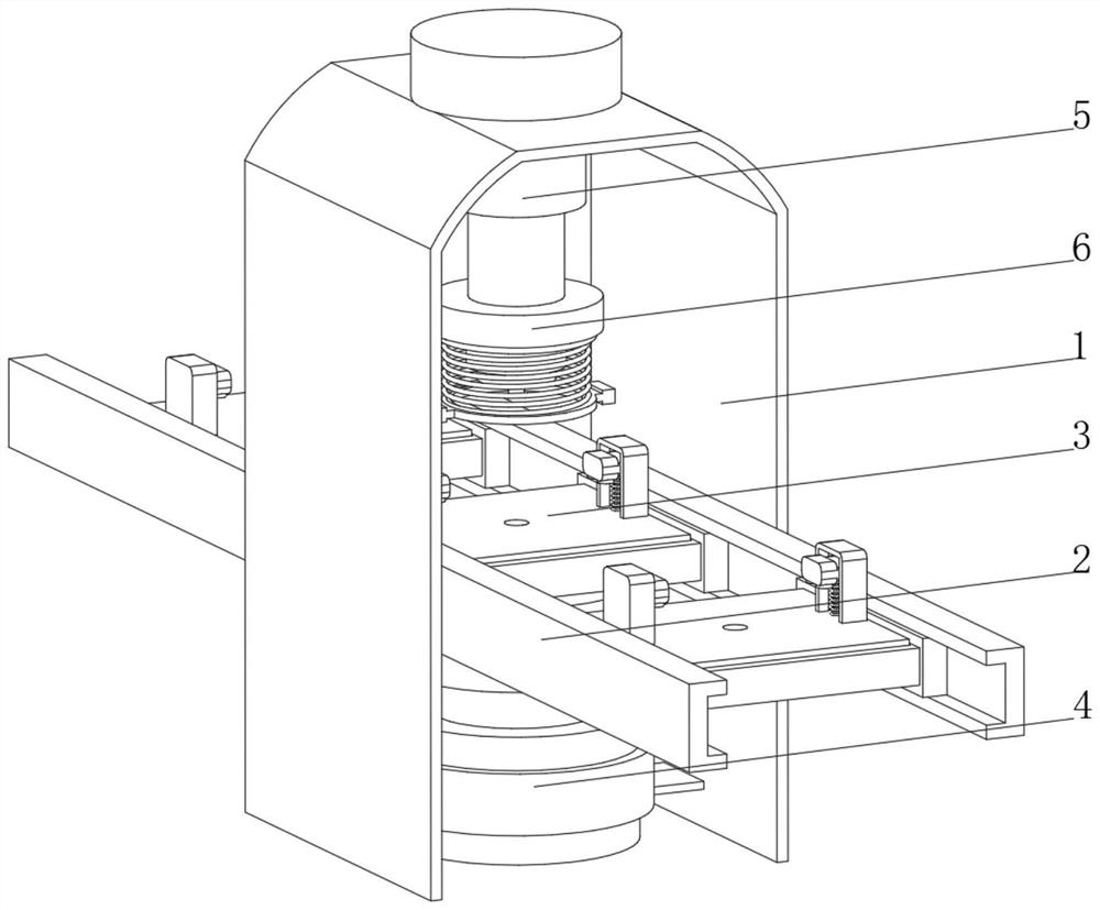
[0044] Hydraulic cylinder 5, the hydraulic cylinder 5 is fixed on the top of the support frame 1, the bottom of the hydraulic cylinder 5 is fixedly connected with a fixed seat 6, and the bottom of the fixed seat 6 is fixedly connected with a punch 7

[0045] Transport unit 3 includes:

[0046] A fixed plate 31, the bottom of the fixed plate 31 is provided with a positioning hole 32, the top of...

Embodiment 2

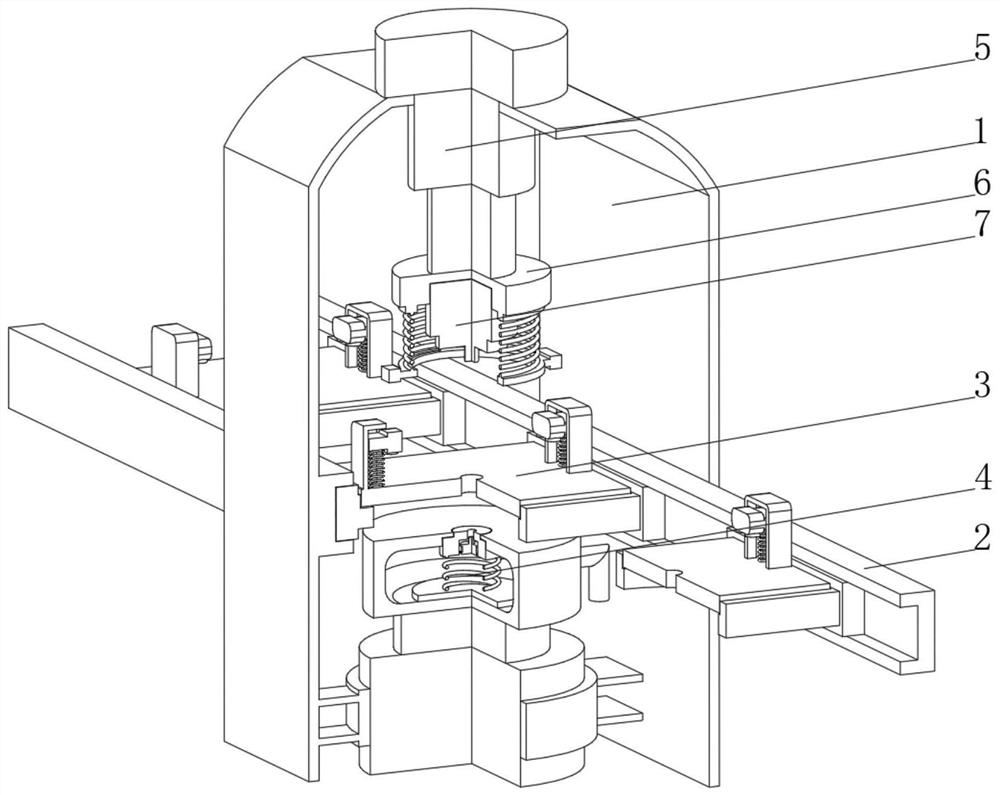
[0053] see Figure 2-5 On the basis of Embodiment 1, the present invention provides a technical solution: the supporting device 4 includes a lifting platform 41, a positioning platform 42 is fixedly connected to the top of the lifting platform 41, and an air cavity 43 is provided inside the positioning platform 42, and the top of the inner wall of the air cavity 43 An air hole 44 is set up, the bottom of the inner wall of the air chamber 43 is fixedly connected with a sealing spring 45, and the top of the sealing spring 45 is fixedly connected with a sealing plug 46 matching the air hole 44. One side of the air chamber 43 is connected with a cooling pipe 47, and the outside of the lifting table 41 The connecting frame is fixedly connected to the inner wall of the support frame 1, and the end of the cooling pipe 47 away from the air chamber 43 is connected with the external cold air pump. The shape and size of the positioning platform 42 are adapted to the positioning hole 32, a...

Embodiment 3

[0055] see Figure 2-6 , on the basis of Embodiment 1 and Embodiment 2, the present invention provides a technical solution: the sealing plug 46 includes a plug body 461, a control groove 462 is opened at the bottom of the plug body 461, and a control motor is fixedly connected to the inner wall of the control groove 462 463, the top of the inner wall of the control groove 462 is provided with a spray hole 464, the inner wall of the spray hole 464 is fixedly connected with a fan-shaped baffle 465, the drive shaft of the control motor 463 extends to the inside of the spray hole 464 and is fixedly connected with a fan-shaped baffle 465. The sealing plate 466, the plug body 461 is set inside the air hole 44 and is slidably connected with the inner wall of the air hole 44, the bottom of the plug body 461 is fixedly connected with the top of the sealing spring 45, the spray hole 464 is set eccentrically inside the control groove 462, and is provided with a sealing plug 46. ​​When t...


PUM


Abstract

The automatic punching equipment for industrial production specifically comprises a supporting frame, a conveying sliding way is fixedly connected to the inner wall of the supporting frame, and a conveying device is slidably connected to the inner wall of the conveying sliding way; the supporting device is arranged in the supporting frame, and the side face of the supporting device is fixedly connected with the inner wall of the supporting frame through a connecting frame; the hydraulic cylinder is fixed to the top of the supporting frame, a fixing seat is fixedly connected to the bottom of the hydraulic cylinder, a punch is fixedly connected to the bottom of the fixing seat, the conveying device comprises a fixing plate, and a positioning hole is formed in the bottom of the fixing plate. According to the automatic punching equipment and method for industrial production, a workpiece can be conveniently positioned and pressed through the pressing block, punching position deviation caused by sliding of the workpiece in the punching process is avoided, the pressing block does not make contact with the workpiece before and after punching, and the workpiece can be conveniently taken and placed.

Description

technical field [0001] The invention relates to the technical field of punching, in particular to an automatic punching device and method for industrial production. Background technique [0002] Punching machine is a kind of mechanical equipment that completes punching with the punching die acting on the material under the drive of the power mechanism after the raw materials are installed. The punching machine can perform sheet processing, stamping, molding, embossing, etc. The operation of metal entering the mold, with the development of high technology, the application field of punching machine is more and more extensive, from the initial defense field and aerospace field to machinery, medical and other fields; according to the shape of the processed material, the punching machine The punching machine is divided into flat punching machine, round tube punching machine, square tube punching machine and U-shaped steel punching machine, etc.; according to the needs of differen...

Claims


Application Information

Patent Timeline
Patent Type & Authority Applications(China)
IPC IPC(8): B21D28/04B21D28/34B21D37/16
Inventor 汪晟
Owner 江苏淮量智能科技有限公司
Why Eureka
Try Eureka