Welding robot

A welding robot and mobile mechanism technology, applied in welding equipment, auxiliary welding equipment, welding/cutting auxiliary equipment, etc.

Pending Publication Date: 2022-04-08
马鞍山市安工大智能装备技术研究院有限公司
View PDF0 Cites 1 Cited by
  • Summary
  • Abstract
  • Description
  • Claims
  • Application Information

AI Technical Summary

Problems solved by technology

Or for welding on both sides of the T-shaped welding surface, this welding method requires both sides of the workpiece to be welded along the extension direction of the weld seam, and requires high-precision horizontal processing of the ground on both sides. Reserve enough space for the welding trolley, and the steering process of the welding trolley needs to be shut down and manually intervened

Method used


Image

  • Welding robot
  • Welding robot
  • Welding robot

Examples


Embodiment Construction

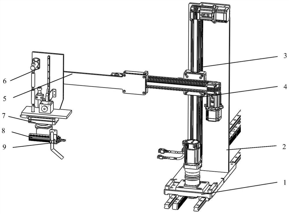
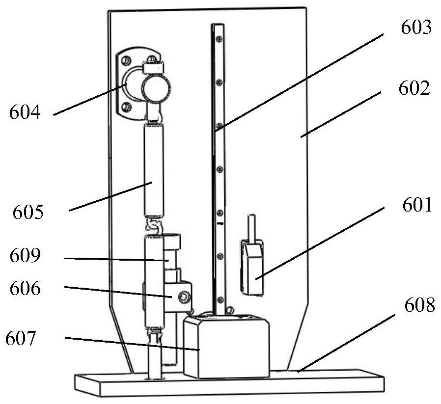
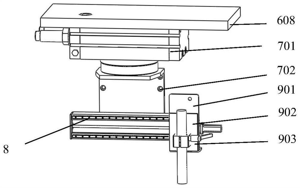
[0020] Such as Figure 1-Figure 5 As shown, a welding robot includes a longitudinal first moving mechanism 1 along the weld seam direction, a sliding base 101 is installed on the output end of the first longitudinal moving mechanism, and the lower end of the vertical vertical plate 2 is fixed on the upper end surface of the sliding base 101 , the base body of the vertical movement mechanism 3 is installed vertically on the vertical riser 2, the collective of the first horizontal movement mechanism 4 is installed on the output end of the vertical movement mechanism 3, the first longitudinal movement mechanism 1 and the first transverse movement mechanism 4 are arranged horizontally and the moving directions of the two are perpendicular to each other. One end of the outrigger plate 5 is installed on the output end of the first horizontal moving mechanism 4, and the outrigger plate 5 is set towards the workpiece to be welded. On the other end of the plate 5, the rotation adjustme...


PUM


Abstract

The invention discloses a welding robot, and belongs to the technical field of automatic welding equipment, the welding robot comprises a longitudinal first moving mechanism in the welding seam direction, a base body of a vertical moving mechanism is vertically arranged and mounted at the output end of the longitudinal first moving mechanism, and a base body of a transverse first moving mechanism is mounted at the output end of the vertical moving mechanism; the longitudinal first moving mechanism and the transverse first moving mechanism are horizontally arranged, the moving directions of the longitudinal first moving mechanism and the transverse first moving mechanism are perpendicular to each other, one end of the outwards-extending plate is installed at the output end of the transverse first moving mechanism, the outwards-extending plate faces a to-be-welded workpiece, and the floating adjusting mechanism is installed at the other end of the outwards-extending plate. The rotary adjusting mechanism is mounted at the lower end of the floating adjusting mechanism, and the floating adjusting mechanism is used for driving the rotary adjusting mechanism to slide in the vertical direction; the swing mechanism is installed at the output end of the rotation adjusting mechanism, and the welding gun clamping mechanism is installed at the output end of the swing mechanism. The device can perform double-sided welding on the T-shaped welding seam and has certain self-adaptive capacity in the vertical direction.

Description

technical field [0001] The invention belongs to the field of automatic welding equipment, and has the design of a welding robot capable of double-sided welding and self-adaptation. Background technique [0002] The existing welding trolley extends along the weld seam direction of the workpiece to be welded. The welding trolley uses a rack and pinion structure to drive and guide the welding torch and its clamping mechanism. This structure has poor stability along the vertical direction, so it is only suitable for The welding seam to be welded is fixed on the same level as the welding trolley. Due to its huge structure, the traditional six-axis welding robot needs an auxiliary large ground rail to adapt to long-distance welding, and the control structure is complicated. [0003] For T-shaped beam welding, it is usually necessary to weld both sides of the T-shaped joint. The current processing method is to let the welding trolley colleagues drive two welding torches that are ...

Claims


Application Information

Patent Timeline
Patent Type & Authority Applications(China)
IPC IPC(8): B23K37/02B25J9/02B25J11/00
Inventor 王璐谢能刚魏伟王萌
Owner 马鞍山市安工大智能装备技术研究院有限公司
Why Eureka
Try Eureka