A buffer displacement mechanism of a laser cutting machine

A laser cutting machine and buffer displacement technology, which is applied to laser welding equipment, metal processing equipment, welding equipment, etc., can solve the problems of affecting cutting progress, cutting head vibration, and long Y-axis moving track, so as to achieve strong practicability and improve Air Quality Effects

Active Publication Date: 2021-08-06
安徽汉超智能装备科技有限公司
View PDF0 Cites 0 Cited by
  • Summary
  • Abstract
  • Description
  • Claims
  • Application Information

AI Technical Summary

Problems solved by technology

In order to improve the cutting efficiency, the laser cutting head needs to move at a high speed. Among them, the moving track of the Y-axis is longer. When moving to both ends at high speed and contacting the limit block, it is easy to generate a large impact force. This impact force is easy to make the cutting head Vibration will affect the cutting progress

Method used


Image

  • A buffer displacement mechanism of a laser cutting machine
  • A buffer displacement mechanism of a laser cutting machine
  • A buffer displacement mechanism of a laser cutting machine

Examples


Embodiment 1

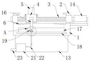
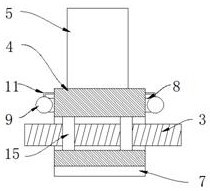
[0028] Refer figure 1 , image 3 and Figure 4 A buffer displacement mechanism of a laser cutting machine includes a cutting machine 1, and a rack plate 13 is provided at the bottom of the cutting machine 1, and a servo motor 14 coupled to the laser cutting machine number is provided on the right side of the cutting machine. The finite position block 2 is provided on both ends of the upper surface of the cutting machine 1, and between the two restricted blocks 2 is rotated by the bearing. The same drive rod 3 is rotated, and the surface of the drive rod 3 is provided with a lateral shock displacement. The block 4, the upper surface of the transverse shock level shifting block 4 is provided with the X-axis cutting frame 5, and the lateral shock displacement block 4 and the driving rod 3 are provided with a rod nut 15, a screw nut 15 and a transverse shock displacement block. 4 fixed connection.

[0029] The upper surface of the cutting machine 1 is provided with a buffer mechanism in...

Embodiment 2

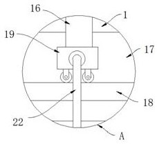
[0034] Refer figure 1 , figure 2 and Figure 5 Unlike Example 1, the front side of the lateral shock displacement block 4 is fixedly connected to the connecting rod 16 on the front side of the cutting machine, and the front side of the cutting machine 1 is opened, and the cutting machine is on the front side and is located The lower portion of the movable hole 17 is provided with a movable flat panel 18, and the bottom portion of the connecting rod 16 is attached to the diaphragm cartridge 19 at the X-axis cutting frame 5, and the bottom portion of the vacuum ceiling box 19 is located The rolling wheel in the upper portion of the movable flat plate 18 is opened with a plurality of vacuum holes 20.

[0035] The front surface of the rack plate 13 is provided with a wind chassis 21, and the inner portion of the wind turbine 21 is provided, the intake end of the suction fan is inner communication with the inside of the dust collector strip 19, and the left side of the wind chassis 21 S...


PUM


Abstract

The invention discloses a buffer displacement mechanism of a laser cutting machine, which comprises a cutting machine table. Limiting blocks are arranged on both ends of the upper surface of the cutting machine table. A driving screw, the surface of the driving screw is covered with a transverse shock-absorbing displacement block, and the upper surface of the transverse shock-absorbing displacement block is provided with an X-axis cutting frame; The interior of the displacement block is provided with a buffer mechanism; the interior of the lateral shock-absorbing displacement block is provided with an automatic buffer assembly extending to both sides of the lateral shock-absorbing displacement block. The mechanism generates magnetic adsorption by setting the magnetic force plate and the deceleration magnet, which has a deceleration effect, and the magnetic force gradually increases, thereby avoiding strong collision between the side of the lateral shock-absorbing displacement block and the limit block; at the same time, a buffer mechanism composed of negative pressure balls is set. , Relying on its own movement to drive the inflation and deflation of the negative pressure ball, the negative pressure ball after inflation is in contact with the limit block, which has the effect of cushioning and shock absorption.

Description

Technical field [0001] The present invention relates to the field of laser cutting machines, and more particularly to a buffer displacement mechanism of a laser cutting machine. Background technique [0002] The laser cutting is a laser beam that will be transmitted from the laser, a light path system, and focusing on a high power density. The laser beam is irradiated to the surface of the workpiece, so that the workpiece reaches the melting point or boiling point, while the high pressure gas coaxial with the beam will blow away the melting or gasification metal. With the movement of the beam and the workpiece, the material is finally formed, thereby achieving the research and development and application of the electric residential building energy saving technology. [0003] During the cutting process, the laser cutting head needs to move in the X-axis and the Y-axis direction according to the graphical graphics. The existing moving mechanism is mostly a driving method of a screw...

Claims


Application Information

Patent Timeline
Patent Type & Authority Patents(China)
IPC IPC(8): B23K26/70B23K26/142B23K26/38
CPCB23K26/38B23K26/142B23K26/702
Inventor 陈宏
Owner 安徽汉超智能装备科技有限公司
Why Eureka
Try Eureka