High-positioning-precision jig for PCD turning tool blade and using method of high-positioning-precision jig

A positioning accuracy and blade technology, applied in the field of PCD, can solve the problems of inconvenient PCB tool position control, inconvenient parts adjustment, and inability to judge PCB tools, etc., to achieve the effect of being suitable for popularization, flexible use, and easy to process

Inactive Publication Date: 2022-04-08
江苏扬碟钻石工具有限公司
View PDF1 Cites 0 Cited by
  • Summary
  • Abstract
  • Description
  • Claims
  • Application Information

AI Technical Summary

Problems solved by technology

[0004] In this embodiment, a jig with high positioning accuracy for PCD turning blades is provided to solve the problem that common jigs in the prior art are inconvenient to adjust parts and control the position of PCB cutters. During processing, the staff cannot judge the specific position of the PCB tool more conveniently and accurately

Method used


Image

  • High-positioning-precision jig for PCD turning tool blade and using method of high-positioning-precision jig
  • High-positioning-precision jig for PCD turning tool blade and using method of high-positioning-precision jig
  • High-positioning-precision jig for PCD turning tool blade and using method of high-positioning-precision jig

Examples


Embodiment Construction

[0029] In order to enable those skilled in the art to better understand the solution of the present application, the technical solution in the embodiment of the application will be clearly and completely described below in conjunction with the accompanying drawings in the embodiment of the application. Obviously, the described embodiment is only It is an embodiment of a part of the application, but not all of the embodiments. Based on the embodiments in this application, all other embodiments obtained by persons of ordinary skill in the art without creative efforts shall fall within the scope of protection of this application.

[0030] It should be noted that the terms "first" and "second" in the description and claims of the present application and the above drawings are used to distinguish similar objects, but not necessarily used to describe a specific sequence or sequence. It should be understood that the data so used may be interchanged under appropriate circumstances for...


PUM


Abstract

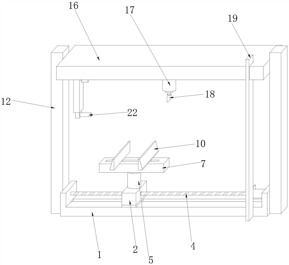
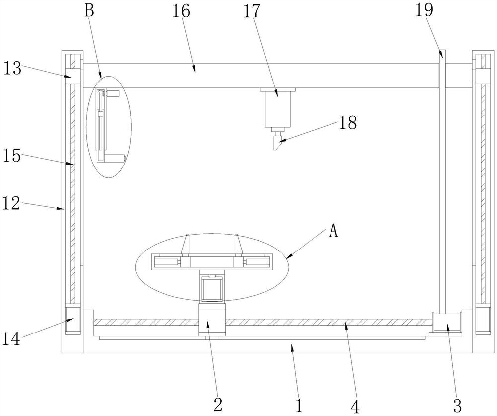
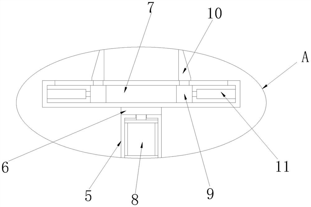
The high-positioning-precision jig comprises a bottom fixing frame, a moving seat, a rectangular supporting column, a lifting cross beam, a clamping and fixing structure, an adjusting structure and a positioning structure, the moving seat is slidably connected to the upper surface of the bottom fixing frame, and the clamping and fixing structure is fixedly mounted on the upper surface of the moving seat; rectangular supporting columns are fixedly connected to the two sides of the bottom fixing frame correspondingly, inner cavities are formed in the rectangular supporting columns, and adjusting structures are installed in the inner cavities of the rectangular supporting columns. The clamping and fixing structure is arranged, a part needing to be machined can be flexibly fixed through the clamping and fixing structure, the position and angle of the part can be flexibly adjusted after fixing, machining is facilitated, the adjusting structure is arranged, the height of a tool can be adjusted through the adjusting structure, and the machining precision is improved. And the cutter is matched with the clamping and fixing structure to grind the part.

Description

technical field [0001] The application relates to the field of PCD, in particular to a jig with high positioning accuracy for PCD turning blades. Background technique [0002] The research on PCD cutting tools was carried out earlier in developed countries, and its application has been relatively mature. Since the first synthesis of synthetic diamond in Sweden in 1953, the research on the cutting performance of PCD tools has achieved a lot of results, and the application range and usage of PCD tools have expanded rapidly. [0003] When the PCB tool is processing the parts, it needs to fix the parts and control the position of the PCB tool at the same time. The traditional fixture is not convenient to adjust the parts and control the position of the PCB tool. At this time, the staff cannot judge the specific position of the PCB tool more conveniently and accurately. Therefore, in view of the above problems, a jig with high positioning accuracy for PCD turning blades is prop...

Claims


Application Information

Patent Timeline
Patent Type & Authority Applications(China)
IPC IPC(8): B23Q3/08B23Q1/25B23Q5/28B23Q17/22B23Q17/24B24B41/06B24B41/00B24B49/00B24B49/12
Inventor 唐健王波吴石李哲张为
Owner 江苏扬碟钻石工具有限公司
Why Eureka
Try Eureka