

Low-wind-resistance wheel and automobile
A wind resistance and wheel technology, applied in the directions of wheels, vehicle parts, transportation and packaging, can solve the problems of insignificant reduction of fuel consumption, inability to close the air vents, and inability to open the brake pads, so as to avoid the air vents being too small and reducing the The effect of improving fuel consumption and improving service life
- Summary
- Abstract
- Description
- Claims
- Application Information
AI Technical Summary
Problems solved by technology
Method used
Image

Examples
Embodiment 1
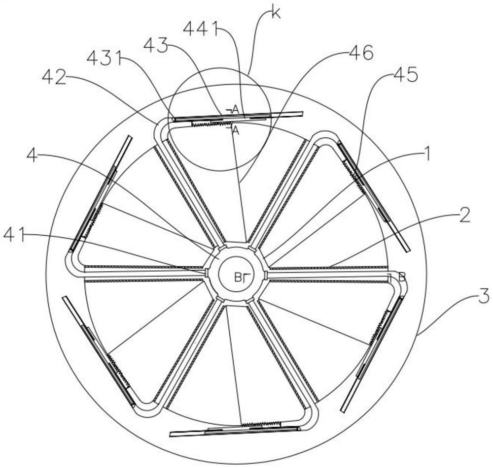
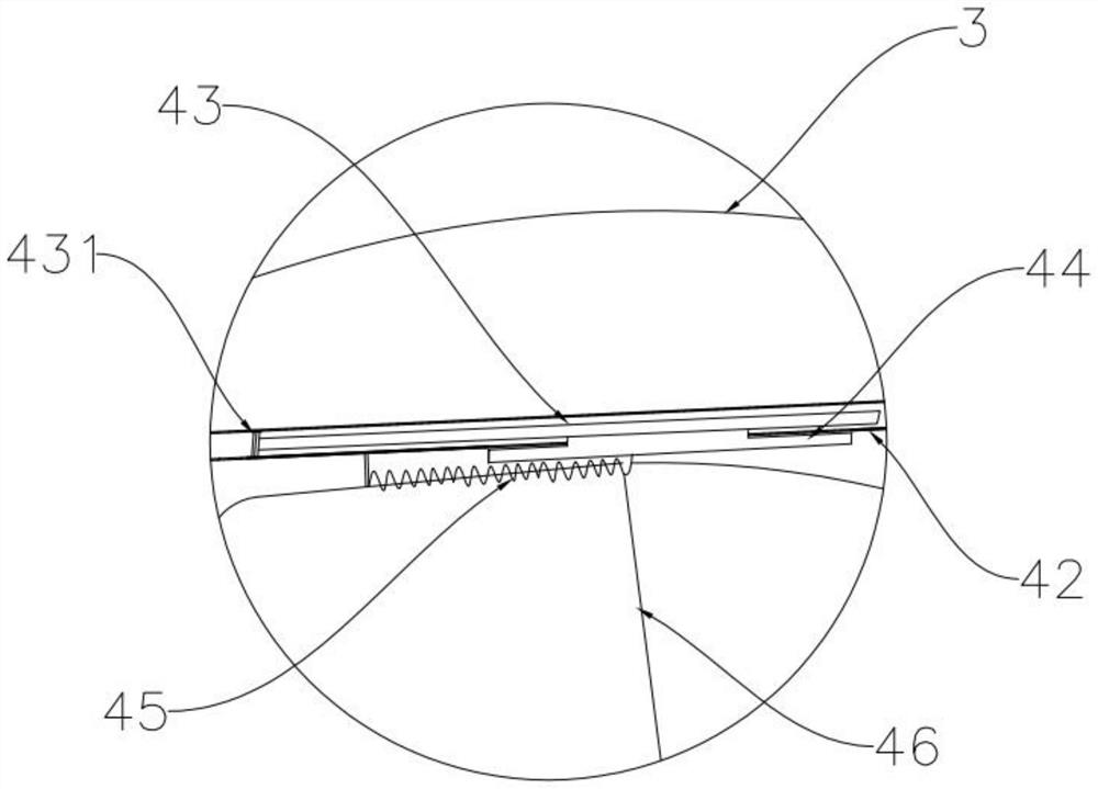
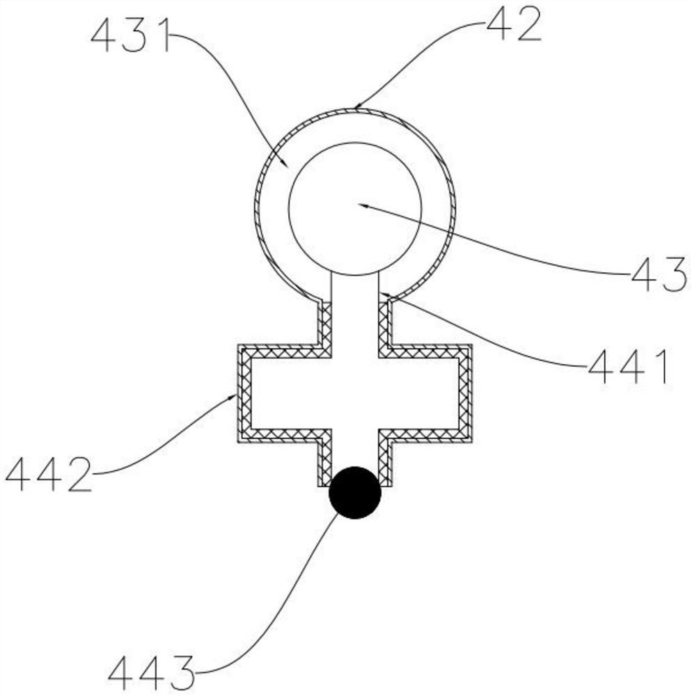
[0024] Example 1, see figure 1 , a low-drag wheel, including a rim 2, a spoke 3 and a hub 1, several spokes 3 are evenly distributed between the rim 2 and the hub 1, and an energy storage bag 4 is installed on the hub 1, each Conduits 42 are installed on the spokes 3, and one end of each of the conduits 42 communicates with the energy storage bag 4, and each of the conduits 42 is connected with a sliding assembly, and the extruding mechanism pushes the energy storage bag. The medium in the bag 4 makes each sliding assembly slide, and drives the end of each curtain 46 connected on the sliding assembly to move to change the wheel air vent.
[0025] Among them, see figure 1 and Figure 4 , the hub 1 is provided with an annular groove, the energy storage bag 4 is located in the annular groove, the side of the energy storage bag 4 away from the bottom of the annular groove is in contact with the extrusion mechanism, and the energy storage bag 4 Several connecting ports are evenl...
Embodiment 2
[0032] Embodiment 2, an automobile, including the above-mentioned low-drag wheels. It should be noted that the vehicle can be a hatchback sedan, a sedan sedan, a pickup truck, an SUV, an MPV, a van or an off-road vehicle of a traditional fuel vehicle or a new energy vehicle.
PUM
 Abstract
Description
Claims
Application Information