
Oil level gauge calibration device

The technology of a calibration device and an oil level gauge, which is applied in the field of oil level gauge inspection, can solve the problems of low resolution of a magnetic flap liquid level gauge, affecting production, affecting the normal operation of a storage tank, etc., and achieving a small overall volume and easy installation. and disassembly, the effect of easy horizontal position adjustment

Pending Publication Date: 2022-04-08
中国测试技术研究院流量研究所
View PDF0 Cites 0 Cited by
  • Summary
  • Abstract
  • Description
  • Claims
  • Application Information

AI Technical Summary

Problems solved by technology

[0002] Due to the low resolution of the magnetic flap level gauge, it is usually equipped with a reed switch level gauge as a remote instrument when used. When we detect the magnetic flap level gauge, we usually need to use the magnetic flap The liquid level gauge can only be tested after being disassembled as a whole. If there is no valve at the connection between the storage tank and the magnetic flap level gauge, it is necessary to drain all the liquid in the storage tank and then disassemble it, so that the storage tank is in a shutdown state. affected the normal production
[0003] At present, the calibration of the magnetic flap liquid level gauge is carried out as a whole, and the overall detection must disassemble the magnetic flap liquid level gauge, which will affect the normal operation of the storage tank.

Method used


Image

  • Oil level gauge calibration device
  • Oil level gauge calibration device
  • Oil level gauge calibration device

Examples


Embodiment

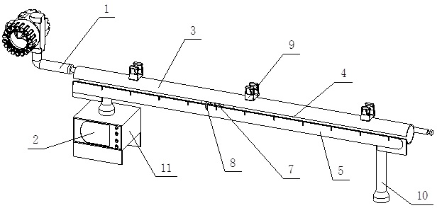
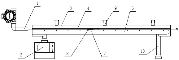
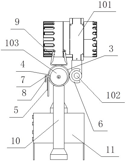
[0023] Such as figure 1 , figure 2 , image 3 and Figure 4 As shown, the oil level gauge calibration device provided in this embodiment includes a magnetostrictive liquid level gauge 1, a dual-channel digital display 2 and a cylinder body 3. The magnetostrictive liquid level gauge 1 includes a meter head 101, a probe Rod 102 and floating ball 103, the two ends of the cylinder 3 are open, the middle part of one side of the cylinder 3 is provided with a bar-shaped groove 4 that runs through the side wall of the cylinder 3, a steel ruler 5 is provided under the bar-shaped groove 4, and a steel ruler 5 The ruler 5 is parallel to the strip groove 4, the top edge of the steel ruler 5 is flush with the bottom edge of the strip groove 4, the steel ruler 5 is fixedly installed on the outer wall of the cylinder 3, and the floating ball 103 is set in the cylinder Inside the body 3, and cooperate with the gap between the inner wall of the cylinder body 3, a handle 7 is installed on t...


PUM


Abstract

The oil level meter calibration device comprises a magnetostriction liquid level meter, a double-channel digital display instrument and a barrel, the two ends of the barrel are open, a strip-shaped groove penetrating through the side wall of the barrel is formed in the middle of one side of the barrel, and a straight steel ruler is arranged below the strip-shaped groove; a plurality of C-shaped elastic buckles are installed on the outer wall of the side, opposite to the strip-shaped groove, of the barrel in the length direction of the barrel, the probe rod is clamped in the elastic buckles, one end of the probe rod is a meter head, the floating ball is sleeved with the barrel, a handle is fixedly connected to the side, close to the strip-shaped groove, of the floating ball, and the handle extends out of the strip-shaped groove. A pointer is further installed at the bottom of the side, close to the gauge head, of the handle, a plurality of fixing buckles are evenly distributed on the top of the barrel in the length direction of the barrel, and the double-channel digital display instrument is connected with the gauge head and the piece to be tested. The device is simple in structure and reasonable in design, the remote transmission part of the magnetic flap liquid level meter can be effectively verified, the magnetic flap liquid level meter does not need to be disassembled, and normal work of the storage tank is guaranteed.

Description

technical field [0001] The invention belongs to the technical field of oil level gauge inspection, and in particular relates to an oil level gauge calibration device. Background technique [0002] Due to the low resolution of the magnetic flap level gauge, it is usually equipped with a reed switch level gauge as a remote instrument when used. When we detect the magnetic flap level gauge, we usually need to use the magnetic flap The liquid level gauge can only be tested after being disassembled as a whole. If there is no valve at the connection between the storage tank and the magnetic flap level gauge, it is necessary to drain all the liquid in the storage tank and then disassemble it, so that the storage tank is in a shutdown state. affected normal production. [0003] At present, the calibration of the magnetic flap liquid level gauge is performed as a whole, and the overall detection requires the disassembly of the magnetic flap liquid level gauge, which affects the norm...

Claims


Application Information

Patent Timeline
Patent Type & Authority Applications(China)
IPC IPC(8): G01F25/00G01F23/62
Inventor 甘蓉郝罗亮李雁灵王彭
Owner 中国测试技术研究院流量研究所
Learn More