Method and equipment for generating road operation condition diagram
A technology for operating conditions and roads, applied in traffic control systems, instruments, and traffic control systems of road vehicles, can solve the problems of low degree of reduction, low efficiency of manual rendering, and cumbersome matching process, so as to improve flexibility, The effect of improving display efficiency and reducing complexity
Pending Publication Date: 2022-04-08
HANGZHOU HIKVISION SYST TECH
7 Cites 0 Cited by
AI-Extracted Technical Summary
Problems solved by technology
Among them, the efficiency of manual drawing is low, and the degree of restoration is not high. At the same time, the process of matching the d...
Abstract
The invention discloses a method and equipment for generating a road operation condition diagram, relates to the field of computer software, and is used for improving the reduction degree in the road operation condition diagram, simplifying the process of manually drawing the matching of a road section and a road condition and improving the display efficiency of the road operation condition diagram. The method comprises the steps of receiving a first operation of a user for a map interface; determining a target road section in response to the first operation; displaying a drawn road section corresponding to the target road section on a drawing interface; acquiring road condition information of the target road section; generating a road operation condition diagram of the target road section; wherein the road operation condition diagram comprises the drawn road section and the corresponding relation between the road condition information of the target road section and the drawn road section.
Application Domain
Road vehicles traffic control
Technology Topic
Computer softwareSystems engineering +3
Image
Examples
- Experimental program(1)
Example Embodiment
[0039] In the description of this application, unless otherwise stated, "/" means "or", for example, A/B can mean A or B. In this article, "and/or" is only an association relationship to describe the associated objects, which means that there can be three kinds of relationships, for example, A and/or B, which can mean that A exists alone, A and B exist at the same time, and B exists alone these three situations. Further, "at least one" means one or more, and "plurality" means two or more. The words "first" and "second" do not limit the quantity and execution order, and the words "first", "second" and the like do not limit certain differences.
[0040] It should be noted that, in this application, words such as "exemplary" or "for example" are used to represent examples, illustrations or illustrations. Any embodiment or design described in this application as "exemplary" or "such as" should not be construed as preferred or advantageous over other embodiments or designs. Rather, the use of words such as "exemplary" or "such as" is intended to present the related concepts in a specific manner.
[0041]The embodiments of the present application provide a method for generating a road operating condition map, which can be applied to computer equipment. The embodiments of the present application do not impose any limitations on the specific form of the computer device. For example, the computer equipment may specifically be a terminal device or a network device. The terminal device may be referred to as: terminal, user equipment (UE), terminal equipment, access terminal, subscriber unit, subscriber station, mobile station, remote station, remote terminal, mobile equipment, user terminal, wireless communication device, user agent, or user device, etc. The terminal device may specifically be a mobile phone, an augmented reality (AR) device, a virtual reality (VR) device, a tablet computer, a notebook computer, an ultra-mobile personal computer (UMPC), a netbook, a personal digital Assistant (personaldigital assistant, PDA) and so on. Specifically, the network device may be a server or the like. The server may be one physical or logical server, or may be two or more physical or logical servers sharing different responsibilities and cooperate with each other to realize various functions of the server.
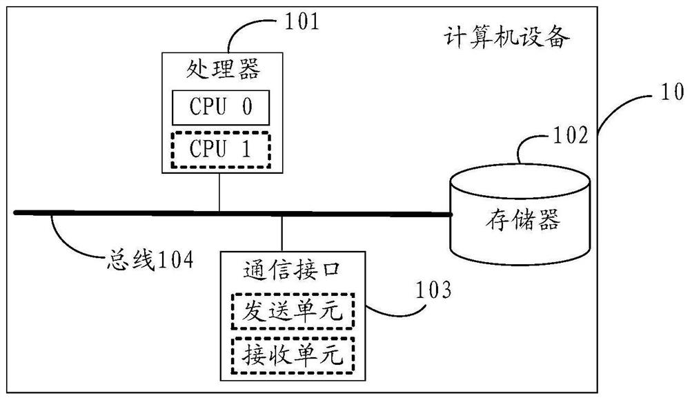
[0042] In terms of hardware implementation, the above-mentioned computer equipment can be implemented through figure 1 The computer equipment shown is implemented. like figure 1 As shown, it is a schematic diagram of a hardware structure of a computer device 10 provided by an embodiment of the present application. The computer device 10 may be used to implement the functions of the computer device described above.
[0043] figure 1 The illustrated computer device 10 may include a processor 101 , a memory 102 , a communication interface 103 , and a bus 104 . The processor 101 , the memory 102 and the communication interface 103 can be connected through a bus 104 .
[0044] The processor 101 is the control center of the computer device 10, and may be a general-purpose central processing unit (central processing unit, CPU), or other general-purpose processors. Wherein, the general-purpose processor may be a microprocessor or any conventional processor or the like.
[0045] As an example, the processor 101 may include one or more CPUs, such as figure 1 CPU 0 and CPU 1 shown in.
[0046] Memory 102 may be read-only memory (ROM) or other type of static storage device that can store static information and instructions, random access memory (RAM), or other type of static storage device that can store information and instructions The dynamic storage device can also be an electrically erasable programmable read-only memory (electrically erasable programmable read-only memory, EEPROM), a magnetic disk storage medium or other magnetic storage devices, or can be used to carry or store data in the form of instructions or data structures. desired program code and any other medium that can be accessed by a computer, but is not limited thereto.
[0047] In a possible implementation manner, the memory 102 may exist independently of the processor 101 . The memory 102 may be connected to the processor 101 through a bus 104 for storing data, instructions or program codes. When the processor 101 invokes and executes the instructions or program codes stored in the memory 102, the method for generating a road operating condition map provided by the embodiments of the present application can be implemented.
[0048] In another possible implementation manner, the memory 102 may also be integrated with the processor 101 .
[0049] The communication interface 103 is used to connect the computer device 10 with other devices through a communication network, the communication network may be Ethernet, radio access network (RAN), wireless local area networks (WLAN) and the like. The communication interface 103 may include a receiving unit for receiving data, and a transmitting unit for transmitting data.
[0050] The bus 104 may be an industry standard architecture (ISA) bus, a peripheral component interconnect (PCI) bus, an extended industry standard architecture (EISA) bus, or the like. The bus can be divided into address bus, data bus, control bus and so on. For ease of presentation, figure 1 is represented by a single thick line, but does not mean that there is only one bus or one type of bus.
[0051] It should be pointed out that, figure 1 The structure shown in does not constitute a limitation to the computer device 10, except figure 1 In addition to the components shown, computer device 10 may include more or fewer components than shown, or some combination of components, or a different arrangement of components.
[0052] In order to make the embodiments of the present application more clear, the following briefly introduces concepts and some contents related to the embodiments of the present application.
[0053] 1. Road network: refers to a networked road system composed of various roads or road sections in a certain area.
[0054] 2. Road operation status: referred to as road conditions, refers to the congestion status of roads or road sections. Road conditions can include clear, relatively clear, slightly congested, moderately congested, and severely congested.
[0055] 3. Road condition screen: It refers to the display screen placed on the road to display the road conditions ahead.
[0056] The above is a brief introduction to some concepts involved in this application.
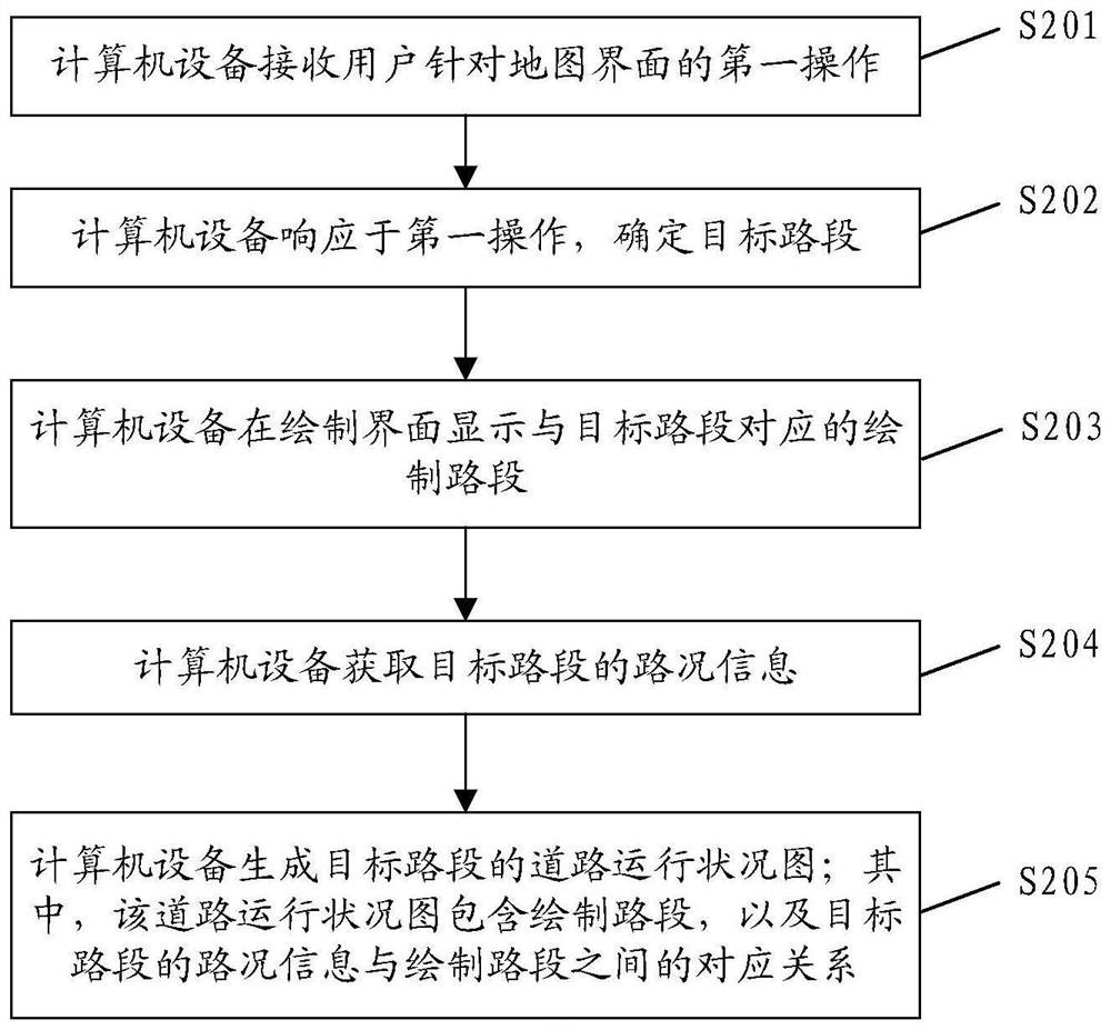
[0057] like figure 2 As shown, it is a flowchart of a method for generating a road operating condition map provided by the present application. The method includes:
[0058] S201. The computer device receives a first operation of a user on a map interface.
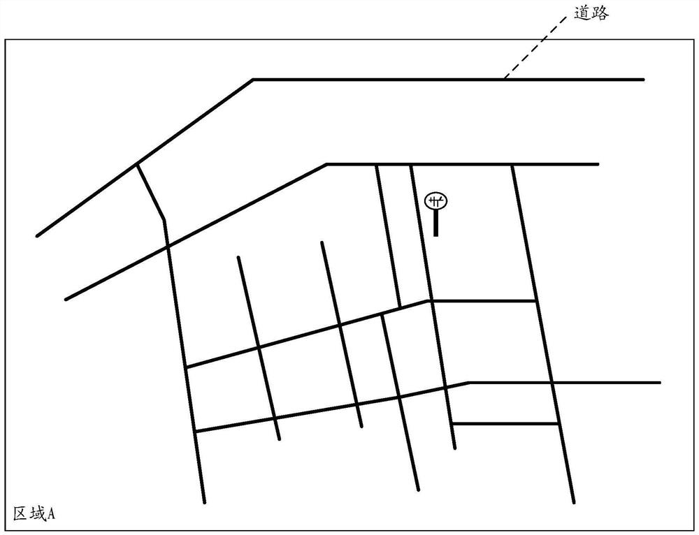
[0059] The map interface refers to the interface including the road network. like image 3 As shown, it is the interface of the road network including a plurality of roads in area A.
[0060] Optionally, the above-mentioned map interface includes identifiers of multiple road segments, and the identifiers of the multiple road segments are the names or unique identifiers (Identity document, ID) of the road segments. For example, the road segment name "Heping Road", or the unique identifier "244927431" represents the road segment.
[0061] Specifically, the first operation is that the user clicks one or more positions on the map interface, or the first operation is to frame one or more areas of the map interface.
[0062] S202. The computer device determines the target road segment in response to the first operation.
[0063] In a first possible implementation manner, the first operation is that the user clicks one or more positions on the map interface, and the computer device selects the first road segment in response to the clicked operation, and uses the first road segment as the target road segment. like Figure 4 In the map interface, the user determines the target road segments AB, CD and EF that need to be displayed on the road condition screen, and selects the road segments from point A to point B, point C to point D, and point E to point F in the map, Figure 4 shown in bold line segments.
[0064] It can be understood that, in this implementation manner, the user selects the target road section by clicking on his/her own, and the selection method includes various methods. For example, the user selects the target road segment AB by clicking and dragging point A to point B in the map interface. For another example, the user clicks point A and then clicks point B in the map interface, and the computer device generates the target road segment AB from A to B according to the order of the user's clicks.
[0065] In the second possible implementation manner, the user performs a frame selection on the map interface, and the first operation is used to indicate the target area. The computer device selects the target area in response to the box selection operation, and the road section included in the target area is used as the target road section. like Figure 5 As shown, the user selects a target area in a box, the target area includes road segments A'B', road segments C'D' and road segments E'F', and the start and end positions of the multiple road segments are selected in the target area. On the edge, the plurality of road segments are used as target road segments.
[0066] In a third possible implementation manner, the user clicks on the map interface, and the computer device automatically selects the first road segment in response to the clicking operation, and uses the first road segment as the target road segment. The position selected by the user on the map interface has a corresponding relationship with the first road segment. The corresponding relationship is preset in the map interface, for example, road segments are divided according to overlapping positions between roads. The overlapping position of each road segment with other road segments is located at the start or end position of the road segment, and does not overlap with other road segments in the middle of each road segment. like Image 6 As shown, the user clicks point A to select road segment aM, clicks point B to select road segment Mb, clicks point C to select road segment cN, clicks point D to select road segment Nd, clicks point E to select road segment eM, clicks point F to select road segment Nf, clicks point G to select segment Section MN. Wherein, the area where the overlapping position is located includes any one of the multiple overlapping road segments. For example, in Image 6 , multiple road segments overlap at points M and N, and when the computer device clicks points M and N, the road segment MN is selected accordingly. The computer device takes the selected road segment as the target road segment.
[0067] For another example, the middle of a road segment overlaps with other road segments. For example, in Image 6 , whether the user clicks point E, point G or point F, it corresponds to the road segment ef. In this application, there is no limitation on the correspondence between the user-clicked position and the road segment.
[0068] Optionally, before the above step S201, the method further includes steps S200a and S200b.
[0069] S200a. The computer device receives a second operation from the user, where the second operation is used to designate a road condition screen that needs to display a road operating condition map.
[0070] Wherein, the user performs the second operation on the road condition screen selection interface. like Figure 7a As shown, it is a road condition screen selection interface, which includes information and operation options of multiple road condition screens. Specifically, the information of the road condition screen includes the serial number in the plurality of road condition screens, the road condition screen name as the unique identifier of the road condition screen, the area to which the road condition screen belongs in the map, and the road condition configuration representing the configuration state of the road condition screen. The operation option is used for the user to perform a second operation to start the configuration of the road condition screen. E.g, Figure 7a The middle is located in multiple road condition screens, the serial number is 1, the road condition screen name is 244927431, its area is area A, and the road condition configuration is not configured.
[0071] It should be noted that the information on the road condition screen may also include more or less information, for example, may also include an organization to which the road condition screen belongs, where the organization to which the road condition screen belongs refers to a department that manages the road condition screen. Alternatively, the information of the road condition screen may be represented by other means. For example, the name of the road condition screen may also be represented by a user-defined character, which is not limited in this application.
[0072] It should be noted that this application does not limit the manner of the second operation, for example, in Figure 7a , the user clicks the operation option in the road condition screen selection interface to indicate the corresponding road condition screen.
[0073]Optionally, the road condition screen selection interface may further include a reference map interface where the road condition screen is located, as a reference for the user to perform the second operation. Specifically, the user performs a third operation on the road condition screen selection interface, and the computer device displays a reference map interface in response to the third operation. Wherein, the present application does not limit the manner of the third operation, for example, in Figure 7a , the user can click the name of the road condition screen or other information on the road condition screen to display the reference map interface of the corresponding road condition screen. Wherein, the reference map interface is used to indicate the location of the road condition screen in the road network of the area to which it belongs. Exemplarily, in response to the user targeting Figure 7a The name of the traffic screen in the click operation is 244927431, and the display is as follows Figure 7b The reference map interface shown. Wherein, the reference map interface may further include the information of the road condition screen and an editing option, and the editing option is used for the user to perform a second operation to start the configuration of the road condition screen.
[0074] S200b. In response to the second operation, the computer device displays a map interface including the location of the road condition screen and the road network associated with the road section screen.
[0075] The road network associated with the road condition screen includes roads near the road condition screen and roads displayed in the road condition screen.
[0076] Optionally, based on the location of the road condition screen, a sign corresponding to the location of the road condition screen is displayed on the map interface.
[0077] Exemplarily, in response to the user targeting Figure 7a Click the operation option corresponding to the traffic screen 244927431, or, in response to the user's Figure 7b Click the Edit option to display something like image 3 The shown map interface includes the map interface of the road network associated with the road condition screen and the identification of the road condition screen.
[0078] S203, the computer device displays the drawn road section corresponding to the target road section on the drawing interface.
[0079] Specifically, the computer device acquires the location information of the target road segment in the map, and based on the location information, displays the drawn road segment corresponding to the target road segment on the drawing interface. Exemplarily, the location information is a set of multiple points forming the target road segment in the map, and the location information includes coordinate information of the multiple points. For example, the coordinate information of multiple points is latitude and longitude information, and the computer equipment converts the latitude and longitude information into plane coordinates.
[0080] Optionally, the drawn road segment exactly matches the target road segment. Specifically, when the location information includes the overall location information of the target road segment, the overall location information of the target road segment is mapped to the drawing interface to obtain the drawn road segment. Wherein, the overall position information of the target road segment includes at least three plane coordinates that constitute the target road segment. For example, the computer equipment maps all the plane coordinates constituting the target road segment in proportion, and the mapped drawn road segment has the same shape as the target road segment. like Figure 8a shown, for Figure 4 The selected target road segments AB, CD and EF are the drawn road segments obtained by mapping. The drawn road section obtained in this way is helpful to restore the shape of the road in the road condition screen, which is convenient to improve the look and feel of the road condition screen.
[0081] Optionally, the drawing interface is used for the user to adjust the display characteristics of the drawn road segment in the interface. Wherein, the display features include at least one of the following: display length, display width, display color, display direction, display curvature and text features. The display length refers to the length of the drawn road segment. Display width refers to the width of the drawn road segment. Display color refers to the color in which the road segment is drawn, wherein different colors can be used to indicate different road conditions. The displayed direction refers to the indicated direction of the drawn road section. It can be understood that the indicated direction of the target road section in the map is different from the direction in the road condition screen observed by the driver. Therefore, the indicated direction of the drawn target road section can be adjusted by adjusting the indicated direction. , adapted to the driver's viewing direction.
[0082] Display curvature refers to the curvature of drawn road segments, including straight lines and curves. Specifically, the curvature of the target road section in the map may be bent to varying degrees. It can be understood that the road condition screen is usually used to indicate the road conditions of one or more road sections ahead to the driver, in order to avoid the bending of some road sections. As a result, the display of road sections is not clear, which interferes with the display of road condition information, and the specific shape of one or more road sections can be adaptively ignored.
[0083] Specifically, when the displayed curvature is a curve, it means that the drawn road segment completely matches the target road segment. When the displayed curvature is a straight line, it means that the drawn road segment does not exactly match the target road segment. When the location information includes the location information of the starting point and the location information of the end point of the target road segment, the location information of the starting point and the location information of the end point are mapped on the drawing interface, and the line connecting the location of the starting point and the location of the end point is used as the drawing road segment. like Figure 8b shown, for Figure 4 The selected target road segments AB, CD, and EF are the drawn road segments obtained by connecting the position information of the starting point of the target road segment and the position information of the end point. Wherein, the computer device can also be automatically adjusted according to the deflection angle between the overall position information of the target road segment AB. For example, in Figure 4 When it is judged that the deflection angle between the plane coordinates constituting the target road segment AB is smaller than the first threshold, the line connecting point A and point B of the target road segment AB is used as the drawn road segment when drawing the road segment. The first threshold can be set by the user, which is not limited in this application.
[0084] The text feature is used to represent at least one of the name of the target road segment and the location information of the target road segment. like Figure 8c shown in Figure 8a On the basis of the target road section EF, the name "Peace Road" is added. It can be understood that the text feature may also include the display direction in the drawing interface. For example, vertical text or horizontal text.
[0085] S204, the computer device acquires the road condition information of the target road segment.
[0086] Optionally, the computer device acquires road condition information of the target road segment based on the location information of the target road segment. Exemplarily, the computer device acquires the identifier of the target road segment based on the location information of the target road segment, and acquires the road condition information of the target road segment according to the identifier of the target road segment.
[0087] It can be understood that the current road condition information has a corresponding relationship with the road segment. Among them, there are many kinds of information representing road conditions. For example, the average driving speed of vehicles in a preset time period in the road section is collected. When the average driving speed is greater than the first threshold, the road section is considered to be unobstructed. When the average driving speed is greater than the second threshold, When it is less than the first threshold, the road section is considered to be slightly congested, and when the average driving speed is less than the second threshold, it is considered that the road section is seriously congested. This application does not limit this.
[0088] Optionally, the computer device receives the correspondence between the identifier of the target road segment and the road condition information. As shown in Table 1 below, it is an example of the correspondence between the identifier of the target road segment and the road condition information.
[0089] Table 1
[0090] road section logo road condition AM 000 00 MB 001 01 EN 010 01 ND 011 11 EM 100 10 MN 101 11 NF 110 10
[0091] Specifically, the flag is used to indicate a road segment, and the road conditions of different road segments have a corresponding relationship with the flag respectively. Exemplarily, four road conditions are shown in Table 1 above, "00" represents a clear state, "01" represents a relatively clear state, "10" represents a slightly congested state, and "11" represents a severely congested state. Then the identification is "000" and the road condition is "00", indicating that the road condition of the road segment AM is in a smooth state.
[0092] It should be noted that the corresponding relationship between the target road segment and the road condition is the same as the corresponding relationship between the road segment to which the target road segment belongs and the road condition. Specifically, as Image 6 As shown, on the map, the road segment AM in the target road segment AB is located in the road segment aM, and the road segment MB is located in the road segment Mb, and the road segment aM and the road segment Mb are the road segments with signs in the map, so, according to the location information of the target road segment AB to determine The identification of the road section includes the identification of the road section aM and the identification of the road section Mb. According to the predefined correspondence between the identifier of the road segment and the road condition, the road condition corresponding to the identifier of the road segment aM (that is, the road condition of the road segment aM) and the road condition corresponding to the identifier of the road segment Mb (that is, the road condition of the road segment Mb) are determined.
[0093] S205. The computer device generates a road operating condition map of the target road segment; wherein the road operating condition map includes the drawn road segment and the corresponding relationship between the road condition information of the target road segment and the drawn road segment.
[0094] Optionally, the corresponding relationship between the road condition information of the target road segment and the drawn road segment includes a first corresponding relationship, where the first corresponding relationship refers to a color representing the road condition of the drawn road segment. For example, in combination with the four road conditions in Table 1 above, they correspond to different colors. Red indicates severe congestion, yellow indicates slight congestion, blue indicates relatively smooth flow, and green indicates smooth flow. The road health map includes painted road segments in different colors. like Figure 9 As shown in the figure, the left oblique line represents the smooth state, the right oblique line represents the relatively smooth state, the grid pattern represents the relatively smooth state, and the black represents the severe congestion state.
[0095] Optionally, the corresponding relationship between the road condition information of the target road segment and the drawn road segment includes a second corresponding relationship, where the second corresponding relationship refers to the road condition of the drawn road segment represented by text. For example, in combination with the four road conditions in Table 1 above, it represents unblocked, relatively unblocked, slightly congested, and severely congested, respectively. It is indicated by text next to the corresponding drawn road segment, such as Figure 10 shown.
[0096] It should be noted that the correspondence between the road condition information of the target road segment and the drawn road segment may also include other methods, which are not limited in this application.
[0097] The computer device generates a road operating condition map based on the above-mentioned location information, road condition information and display characteristics.
[0098] After the above step S205, the computer device sends the information of the road operating condition map to the road condition screen, and the road operating condition graph is displayed on the road condition screen. The information of the road operation status map refers to any kind of information that can display an image, which is not limited in this application.
[0099] The solutions of the embodiments of the present application have been introduced above mainly from the perspective of methods. It can be understood that, in order to realize the above-mentioned functions, the computer device includes at least one of corresponding hardware structures and software modules for executing each function. Those skilled in the art should easily realize that the present application can be implemented in hardware or a combination of hardware and computer software with the units and algorithm steps of each example described in conjunction with the embodiments disclosed herein. Whether a function is performed by hardware or computer software driving hardware depends on the specific application and design constraints of the technical solution. Skilled artisans may implement the described functionality using different methods for each particular application, but such implementations should not be considered beyond the scope of this application.
[0100] In this embodiment of the present application, the computer device may be divided into functional units according to the foregoing method examples. For example, each functional unit may be divided corresponding to each function, or two or more functions may be integrated into one processing unit. The above-mentioned integrated units may be implemented in the form of hardware, or may be implemented in the form of software functional units. It should be noted that the division of units in the embodiments of the present application is illustrative, and is only a logical function division, and other division methods may be used in actual implementation.
[0101] Exemplary, Figure 11 A possible structural schematic diagram of the computer device (referred to as the computer device 110 ) involved in the above embodiment is shown, the computer device 110 includes a receiving unit 1101 , a determining unit 1102 , a display unit 1103 , an acquiring unit 1104 and a generating unit 1105. The receiving unit 1101 is configured to receive a user's first operation on the map interface. E.g, figure 2 shown in step S201. The determining unit 1102 is configured to determine the target road segment in response to the first operation. E.g, figure 2 shown in step S202. The display unit 1103 displays the drawn road section corresponding to the target road section on the drawing interface. E.g, figure 2shown in step S203. The obtaining unit 1104 is configured to obtain road condition information of the target road segment. E.g, figure 2 shown in step S204. The generating unit 1105 is configured to generate a road operating condition map of the target road segment, wherein the road operating condition map includes the drawn road segment and the corresponding relationship between the road condition information of the target road segment and the drawn road segment. E.g, figure 2 shown in step S205.
[0102] Optionally, the receiving unit is further configured to receive a second operation from the user, where the second operation is used to specify a road condition screen that needs to display the road operating condition map; the display unit is further configured to respond to the second operation and display the location including the road condition screen. And the map interface of the road network associated with the traffic screen.
[0103] Optionally, the display unit is further configured to display, on the map interface, an identifier corresponding to the location of the road condition screen based on the location of the road condition screen.
[0104] Optionally, the first operation is used to indicate the first road segment in the map interface; then, in response to the first operation, determining the target road segment, including: taking the first road segment as the target road segment; or, the first operation is used to indicate the map interface. the target area, then in response to the first operation, determining the target road segment includes: taking the road segment included in the target area as the target road segment.
[0105] Optionally, the display unit is specifically configured to acquire position information of the target road section in the map; based on the position information, display the drawn road section corresponding to the target road section on the drawing interface.
[0106] Optionally, the display unit is specifically used to map the drawing interface based on the location information to obtain the drawn road segment; or, based on the starting location and the ending location in the location information, use the connection between the starting location and the ending location as the drawing segment. .
[0107] Optionally, the determining unit is further configured to determine the display characteristics of the drawn road segment in the road operating condition map, where the display characteristics include at least one of the following: display length, display width, display color, display direction, display curvature and text characteristics, The display curvature includes straight lines and curves; the text feature is used to represent at least one of the name of the target road segment and the location information of the target road segment; and a road operating condition map is generated based on the drawn road segment and the display feature.
[0108] Optionally, the computer device 110 further includes a storage unit 1106 . The storage unit 1106 is used to store computer-executed instructions, and other units in the computer device can perform corresponding actions according to the computer-executed instructions stored in the storage unit 1106 .
[0109] For the specific description of the foregoing optional manners, reference may be made to the foregoing method embodiments, which will not be repeated here. In addition, the explanation of any one of the computer devices 110 provided above and the description of the beneficial effects may refer to the corresponding method embodiments above, and will not be repeated.
[0110] As an example, combining figure 1 , some or all of the functions implemented in the receiving unit 1101 , the determining unit 1102 , the displaying unit 1103 , the acquiring unit 1104 , the generating unit 1105 and the storage unit 1106 in the computer device 110 can be implemented by figure 1 The processor 101 in the execution figure 1 The program code in the memory 102 is implemented. The receiving unit 1101 can also pass figure 1 The receiving unit in the communication interface 103 in .
[0111] Embodiments of the present application also provide a computer-readable storage medium, where a computer program is stored on the computer-readable storage medium, and when the computer program runs on a computer, the computer is made to execute any one of the computer devices provided above. method performed.
[0112] For the explanation of the relevant content and the description of the beneficial effects in any of the computer-readable storage media provided above, reference may be made to the above-mentioned corresponding embodiments, which will not be repeated here.
[0113] The embodiment of the present application also provides a chip. The chip integrates a control circuit and one or more ports for implementing the functions of the computer device 110 described above. Optionally, for the functions supported by the chip, reference may be made to the above, which will not be repeated here. Those of ordinary skill in the art can understand that all or part of the steps for implementing the above embodiments can be completed by instructing relevant hardware through a program. The described program can be stored in a computer-readable storage medium. The above-mentioned storage medium may be a read-only memory, a random access memory, or the like. The above-mentioned processing unit or processor can be a central processing unit, a general-purpose processor, an application specific integrated circuit (ASIC), a microprocessor (digital signal processor, DSP), a field programmable gate array (FPGA, FPGA) ) or other programmable logic devices, transistor logic devices, hardware components, or any combination thereof.
[0114] The embodiments of the present application also provide a computer program product containing instructions, when the instructions are run on a computer, the instructions cause the computer to execute any one of the methods in the foregoing embodiments. The computer program product includes one or more computer instructions. When the computer program instructions are loaded and executed on a computer, the procedures or functions according to the embodiments of the present application are generated in whole or in part. The computer may be a general purpose computer, a special purpose computer, a computer network, or other programmable device. Computer instructions may be stored in or transmitted from one computer-readable storage medium to another computer-readable storage medium, for example, the computer instructions may be transmitted from a website site, computer, server, or data center over a wire (e.g. Coaxial cable, optical fiber, digital subscriber line (DSL)) or wireless (eg infrared, wireless, microwave, etc.) means to transmit to another website site, computer, server or data center. Computer-readable storage media can be any available media that can be accessed by a computer or data storage devices including one or more servers, data centers, etc., that can be integrated with the media. Useful media may be magnetic media (eg, floppy disks, hard disks, magnetic tapes), optical media (eg, DVDs), or semiconductor media (eg, SSDs), and the like.
[0115] It should be noted that the above-mentioned devices for storing computer instructions or computer programs provided in the embodiments of the present application, such as but not limited to, the above-mentioned memory, computer-readable storage medium, and communication chip, etc., are all non-transitory (non-transitory) .
[0116] In the above-mentioned embodiments, it may be implemented in whole or in part by software, hardware, firmware or any combination thereof. When implemented using a software program, it can be implemented in whole or in part in the form of a computer program product. The computer program product includes one or more computer instructions. When the computer program instructions are loaded and executed on a computer, the procedures or functions according to the embodiments of the present application are generated in whole or in part. The computer may be a general purpose computer, a special purpose computer, a computer network, or other programmable device. Computer instructions may be stored in or transmitted from one computer-readable storage medium to another computer-readable storage medium, for example, the computer instructions may be transmitted from a website site, computer, server, or data center over a wire (e.g. coaxial cable, optical fiber, digital subscriber line (DSL)) or wireless (eg infrared, wireless, microwave, etc.) means to another website site, computer, server or data center. Computer-readable storage media can be any available media that can be accessed by a computer or data storage devices including one or more servers, data centers, etc., that can be integrated with the media. Useful media may be magnetic media (eg, floppy disks, hard disks, magnetic tapes), optical media (eg, DVDs), or semiconductor media (eg, solid state disks (SSDs)), and the like.
[0117] Although the application is described herein in conjunction with various embodiments, in practicing the claimed application, those skilled in the art can understand and implement the disclosure by reviewing the drawings, the disclosure, and the appended claims Other variations of the embodiment. In the claims, the word "comprising" does not exclude other components or steps, and "a" or "an" does not exclude a plurality. A single processor or other unit may fulfill the functions of several items recited in the claims. The mere fact that certain measures are recited in mutually different dependent claims does not indicate that these measures cannot be combined to advantage.
[0118] Although the application has been described in conjunction with specific features and embodiments thereof, it will be apparent that various modifications and combinations can be made therein without departing from the spirit and scope of the application. Accordingly, this specification and drawings are merely exemplary illustrations of the application as defined by the appended claims, and are deemed to cover any and all modifications, variations, combinations or equivalents within the scope of this application. Obviously, those skilled in the art can make various changes and modifications to the present application without departing from the spirit and scope of the present application. Thus, if these modifications and variations of the present application fall within the scope of the claims of the present application and their equivalents, the present application is also intended to include these modifications and variations.
PUM


Description & Claims & Application Information
We can also present the details of the Description, Claims and Application information to help users get a comprehensive understanding of the technical details of the patent, such as background art, summary of invention, brief description of drawings, description of embodiments, and other original content. On the other hand, users can also determine the specific scope of protection of the technology through the list of claims; as well as understand the changes in the life cycle of the technology with the presentation of the patent timeline. Login to view more.
Similar technology patents
Method and device for controlling control operation
Owner:XIAOMI INC
Security policy setting and determining method, and method and device for executing operation by application program
Owner:CHINA MOBILE COMM CO LTD
Method and device for adding video effect, terminal device and storage medium
Owner:BEIJING BYTEDANCE NETWORK TECH CO LTD
Self-cleaning control method of cleaning equipment, cleaning equipment and storage medium
Owner:TIANKE INTELLIGENT TECH CO LTD
Data filter and combination method
Owner:BEIJING VENUS INFORMATION TECH +1
Classification and recommendation of technical efficacy words
- reduce complexity
- increase flexibility
Identifying software execution behavior
Owner:ACCESSDATA GRP INC
Thin client intelligent transportation system and method for use therein
Owner:PETRISOR GREGORY C +2
Transferring execution from one instruction stream to another
Owner:ADVANCED SILICON TECH
Superposition coding
Owner:MOTOROLA MOBILITY LLC
Airgap-containing interconnect structure with patternable low-k material and method of fabricating
Owner:GLOBALFOUNDRIES INC
Front illuminated back side contact thin wafer detectors
Owner:OSI OPTOELECTRONICS
Security guarantee method and system for Windows terminals based on auto white list
Owner:SHENZHEN Y& D ELECTRONICS CO LTD
Precise positionable and compensable heavy-load mechanical arm
Owner:CHONGQING JIAOTONG UNIVERSITY
Method, a system and a device for converting speech
Owner:DICTA DIRECT LLC