Scanning driving circuit, driving circuit, display panel and display device

A scanning drive circuit and capacitor technology, applied in the field of scan drive circuits, display panels and display devices, and drive circuits, can solve problems affecting the brightness uniformity of the display panel, etc., to improve brightness uniformity, increase pixel compensation time, and increase output The effect of the duration of the low level

Active Publication Date: 2022-04-08
YUNGU GUAN TECH CO LTD
View PDF10 Cites 0 Cited by
  • Summary
  • Abstract
  • Description
  • Claims
  • Application Information

AI Technical Summary

Problems solved by technology

When the refresh rate is high, the existing scanning drive circuit will affect the brightness uniformity of the display panel

Method used


Image

  • Scanning driving circuit, driving circuit, display panel and display device
  • Scanning driving circuit, driving circuit, display panel and display device
  • Scanning driving circuit, driving circuit, display panel and display device

Examples


Embodiment Construction

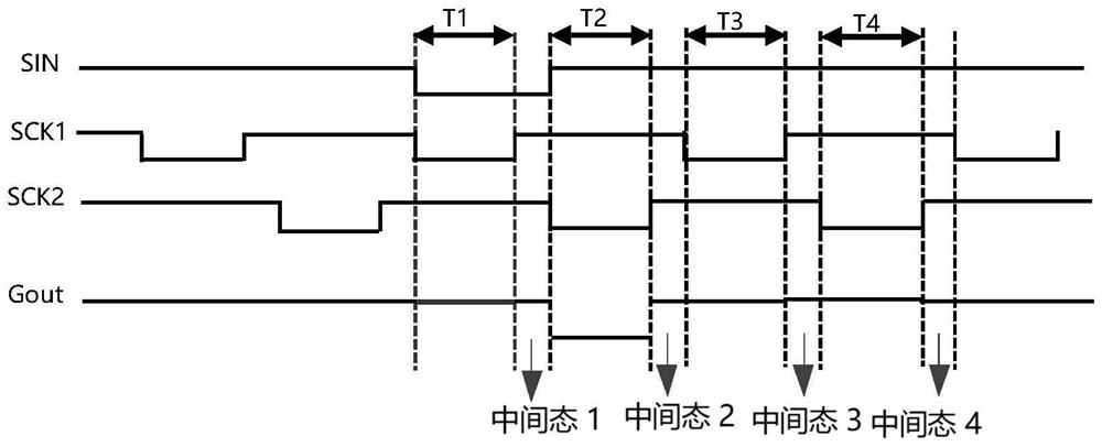
[0056] As mentioned in the background technology, the inventors have found through long-term research that the scanning drive circuit in the related art outputs a low voltage for a short time, which easily leads to insufficient pixel compensation time and reduces the brightness uniformity of the display panel. The main reason for this problem is The reason is that the intermediate state before the scanning drive circuit outputs the low voltage takes a long time, resulting in a short time for the scanning drive circuit to output the low voltage, reducing the pixel compensation time, resulting in inconsistent brightness of pixels in different regions, and reducing brightness uniformity.

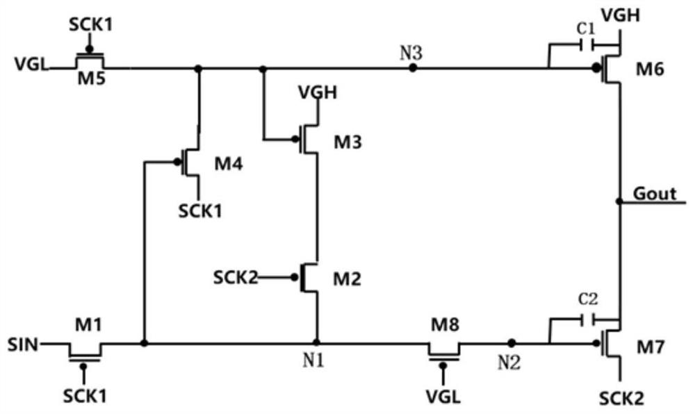
[0057] figure 1 It is a schematic structural diagram of a scanning driving circuit in the related art, such as figure 1 as shown in figure 1 As shown, the scan driving circuit includes transistors M1, M2, M3, M4, M5, M6, M7 and M8, and capacitors C1 and C2.

[0058] One end of the transistor ...


PUM


Abstract

The invention provides a scanning driving circuit, a driving circuit, a display panel and a display device, and relates to the technical field of display panels. In the scanning driving circuit, an input module is respectively connected with a first clock signal input end, an initial input signal end, a second control module, a third control module and a second output module; the first control module is respectively connected with a low potential input end, a first clock signal input end, the second control module, the third control module and the first output module; the second control module is respectively connected with a third clock signal input end, a high potential input end and the first output module; the third control module is respectively connected with the second clock signal input end, the high potential input end and the second output module; the first output module is respectively connected with the high potential input end and the output signal line; and the second output module is respectively connected with the second clock signal input end and the output signal line. Through the arrangement mode, the brightness uniformity of the display panel can be effectively improved.

Description

technical field [0001] The present application relates to the technical field of display panels, and in particular to a scan driving circuit, a driving circuit, a display panel and a display device. Background technique [0002] Organic Light Emitting Diode (OLED) display panel has self-illumination, low driving voltage, high luminous efficiency, short response time, high definition and contrast, near 180° viewing angle, wide operating temperature range, and can realize flexible display With many advantages such as large-area full-color display, it is recognized by the industry as the display panel with the most development potential. The ability of the scan driving circuit to maintain stable and effective work is a key consideration in improving the performance of the display panel. [0003] At present, the development trend of the refresh rate of the display panel of the display device is 1 Hz to 120 Hz, for example, 1 Hz is used for watching static pictures, and 120 Hz i...

Claims


Application Information

Patent Timeline
Patent Type & Authority Applications(China)
IPC IPC(8): G09G3/3266G09G3/3225
Inventor 鲁建军
Owner YUNGU GUAN TECH CO LTD
Why Eureka
Try Eureka